Connector and method for connecting building structures using connector

a technology of connecting structure and connecting rod, applied in the direction of connecting rods, manufacturing tools, mechanical instruments, etc., can solve the problems of lack of workability, large fitting size, lack of transporting characteristic,

Inactive Publication Date: 2000-09-19
KB HOME
View PDF13 Cites 34 Cited by
  • Summary
  • Abstract
  • Description
  • Claims
  • Application Information

AI Technical Summary

Problems solved by technology

However, the above-mentioned related art connector or joint structure had a problem that a large number of parts such as bolts, nuts or washers were used during the work, their fixing work was complicated and the process was lack of workability.
In addition, the prior art had a problem that the fitting was large size, heavy in weight, lacked in transporting characteristic and further lacked in safety characteristic at a high elevated location.
In addition, the prior art had some problems that an erroneous fitting for the fitting and the like occurred to require a certain trouble, it was hard to bury the fitting to a predetermined location in the cylinder or the plug member punched at the predetermined location and make a threadable fitting of bolts to the punched holes in the aforesaid buried cylinder or plug, resulting in that its workability was poor, it required a large number of steps of work and it required a long work period.
The assembly in which the wooden members were fixed with nuts had some problems that their fastening force was lost in several years due to a shrinkage of the wood, looseness could easily occur and their physical strength was reduced.
Additionally, there were some problems that metallic portions such as bolts, nuts or fittings were oxidized by dew and the like, their durability was lost and at the same time the imported wood contained salt due to storage on the sea, the bolts or fittings and the like were decayed to deteriorate physical strength and at the same time durability was lost.
In addition, the prior art system had some problems in disaster prevention that the external connecting bolts or fittings were melted during fire, their strength could not be expected and a housing might be fallen.
In addition, the maximum disadvantage of the framework structure using wooden members was brittleness at the connection part, various kinds of joints or couplers were devised in the past by the carpenters and the like in order to keep a physical strength.
However, all these structures had some problems that they were complex, their machining required a large amount of steps and they showed a poor productivity.
In addition, the prior art had some problems that the wood with large size was poor in its production volume, its availability was difficult and a long and large span beam arch or truss made of wood or laminated wood and the like could not be transported under the traffic regulation and the like.
However, it was found that although the aforesaid inventions have remarkably improved workability, working characteristic and productivity as compared with those of the prior art fittings or working methods and they are remarkably superior in view of effect of anti-disaster or increasing of withstand force, it had the following problems in view of anti-disaster characteristic.
That is, it was found that if bending, tension, compression and shearing and the like act on the structural members such as wooden members, the adhesive agent integrally formed with the connector resists against bending, tension, compression and shearing and the like up to a limit in which the wood is broken, thereafter the adhesive agent and the timber fiber are cut to produce a primary breakage, resulting in that their connecting power is lost and the breakage advances.
In particular, it was found that the prior art system had a problem in which the connection part between the structural members in the region having frequent occurrence of earthquake, the portions with weak withstand force are broken in sequence, accumulated and then a housing is damaged abruptly by earthquake and the like.
When the adhesive agent was fed under pressurized condition in order to perform a smooth returning-back of the adhesive agent, it was found that there was a problem that a certain number of connectors were pushed out in response to a size or a shape of the connector, and when an adhesive agent gun was pulled out, a certain number of connectors were pulled out together with the gun if the diameter of the connection hole was large and then a workability was reduced a little.
In addition, furniture such as closets or chairs, doors or various fittings, playing elements such as jungle gyms or sliders and wooden curved dolls and other fittings having thick-wall portions had some problems that their connecting strength was weak and they lacked in durability due to the fact that each of the members was merely adhered with adhesive agent or merely adhered after a simple process.

Method used


Image

  • Connector and method for connecting building structures using connector
  • Connector and method for connecting building structures using connector
  • Connector and method for connecting building structures using connector

Examples


embodiment 1

Preferred Embodiment 1

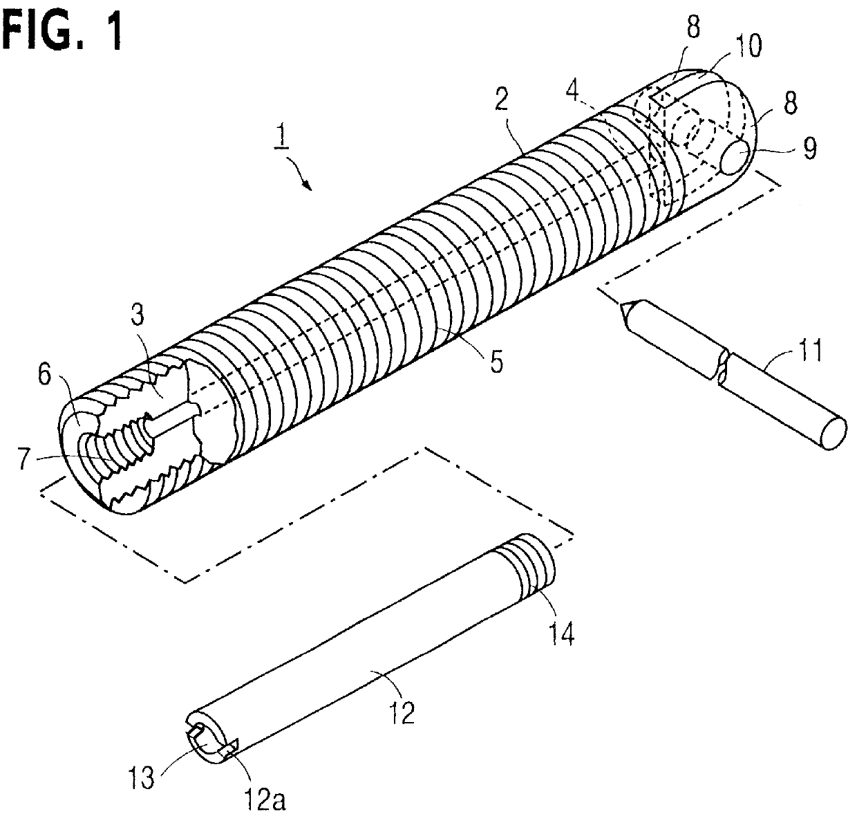
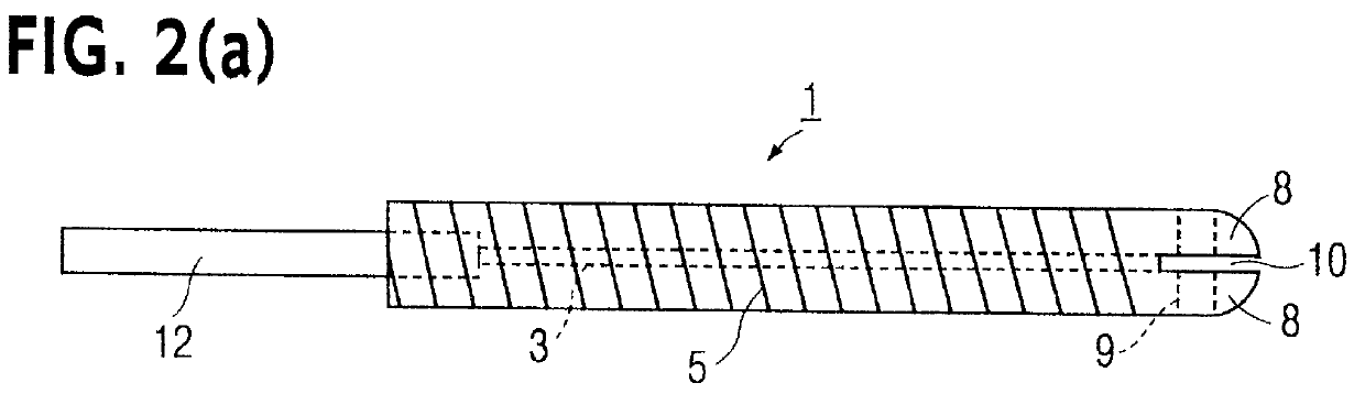
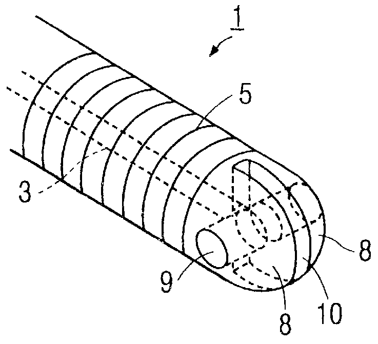
FIG. 1 is a perspective view partly broken-away for showing the connector of the first preferred embodiment of the present invention, FIG. 2(a) is a side elevational view of FIG. 1, FIG. 2(b) is a perspective view for showing a substantial part of an adhesive agent flowing-out hole, FIG. 3 is a front elevational view for showing a substantial part of the adhesive agent flowing-out hole so as to illustrate examples of application of the rod-like member of the connector, and FIG. 4 is a side elevational view for showing a substantial part so as to illustrate examples of application of the insertion hole for fixing member of the connector.

1 denotes a metallic connector of the first preferred embodiment; 2 a metallic rod-like member; 3 a hollow part of the rod like member 2 formed at a substantial central part in a longitudinal direction of the rod-like member 2 and opened at both ends for flowing adhesive agent; 4 an adhesive agent flowing-out hole opened at one e...

embodiment 2

Preferred Embodiment 2

FIG. 7 is a perspective view for showing the connector in the second preferred embodiment of the present invention.

3 denotes a hollow part; 4 an adhesive agent flowing-out hole part; 5 convex or concave portions; 8 a convex wall part; 9 a fixing member insertion and fixing hole; 10 an adhesive agent guiding groove; 12 a branch pipe; 12a an engaging groove; 13 a branch pipe hollow part; 14 an engaging part. These members are similar to those of the preferred embodiment 1, same reference numerals are applied and their description will be eliminated.

1a denotes the metallic connector of the second preferred embodiment in which the branch pipe is engaged with the branch pipe engaging part 7a formed at a predetermined part in a longitudinal direction of the rod-like member 2a, and there are provided adhesive agent flowing-out holes 4 at both ends; 2a a metallic rod-like member of hollow round bar; 7a a branch pipe engaging part formed at a substantial central part of...

embodiment 3

Preferred Embodiment 3

FIG. 10(a) is a side elevational view for showing the connector of the third preferred embodiment of the present invention. FIG. 10(b) is a perspective view for showing a substantial part of the adhesive agent flowing-out hole of the connector of the third preferred embodiment of the present invention.

1b denotes the connector of the third preferred embodiment; 2b a rod-like member; 3 a hollow part formed from one end of the rod-like member 2b to be communicated with the other end thereof; 8b an expanded part of the adhesive agent flowing-out part of the rod-like member 2b; 9 a fixing member insertion and fixing hole formed at the expanded part 8b; 12 a branch pipe fixed to or removably engaged with one end of the rod-like member 2b; 27 an adhesive agent flowing-out hole communicated with the hollow part 3, formed to be crossed with the hollow part 3 or slantly crossed toward the top part of the expanded part 8b; and 27a an adhesive agent flowing-out groove form...


PUM


Abstract

PCT No. PCT/JP94/02107 Sec. 371 Date Aug. 15, 1995 Sec. 102(e) Date Aug. 15, 1995 PCT Filed Dec. 15, 1994 PCT Pub. No. WO95/16834 PCT Pub. Date Jun. 22, 1995It is an object of the present invention to provide a connector in which a strong connection can be carried out with a simple working method, a removal of the connector is eliminated, its workability is remarkably improved, a productivity of building structure is improved, an instantaneous breakage caused by earthquake and the like is prevented and a remarkable anti-disaster effect is attained. The connector (1) of the present invention is comprised of the rod-like member (2), one or two arcular convex walls (8) cooperatively connected to one end of the rod-like member (2) in a longitudinal direction, the hollow part (3) formed from one end to the other end of the rod-like member (2), the insertion hole for fixing member (9) formed at the convex walls (8), and a hollow branch pipe (12) fixed to or removably engaged with the opening of the hollow part (3) at the other end of the rod-like member (2).

Description

1. Technical Field of the InventionThis invention relates to a connector for use in connecting between wooden materials, laminated wood or stone materials, or connecting between a wooden material or laminated wood and a stone material or concrete, and a method for connecting in a building structure in a joint or a coupler structure of a building structure such as a wooden house and a framework structure in a large-sized wooden building with large size structure.2. Background of the Related ArtIn recent years, there have been developed to provide a connector for connection between a beam and a pole plate, a pole beam and a column, and a lateral beam and an independent column (long column) aiming at labor saving and rationalization in building construction work for a dwelling and the like or a joint structure or a coupler structure and the like aiming at a rationalization of construction work.For example, (1) Japanese Utility Model Laid-Open No. Sho 63-162008 discloses a framework fit...

Claims


Application Information

Patent Timeline
Patent Type & Authority Patents(United States)
IPC IPC(8): E04B1/48F16B11/00E04B1/26
CPCE04B1/48F16B11/006Y10T403/473Y10T403/55Y10T403/46E04B1/483E04B1/486
Inventor GOTO, YASUO
Owner KB HOME
Why Eureka
Try Eureka