Spinal support system for seating

Inactive Publication Date: 2000-10-03
WALKER BROCK M +1
View PDF82 Cites 90 Cited by
  • Summary
  • Abstract
  • Description
  • Claims
  • Application Information

AI Technical Summary

Problems solved by technology

Back pain has many causes, but few cures.
In either case, the resulting stress can be due to inappropriately applied pressure or due to a distorted or damaged spinal column that has existed for varying periods of time, with resulting pain depending on the prior state of the spinal cord.
Thus, the resistance provided by the Meares device is not uniform.
As the body undergoes changes when getting into a seat and when seated, especially if one is to perform functions while in a seated position, the normal curvature of the spine is generally distorted.
This is due to the fact that many, if not most, chairs do not give good spinal support.
Consequently

Method used


Image

  • Spinal support system for seating
  • Spinal support system for seating
  • Spinal support system for seating

Examples


Embodiment Construction

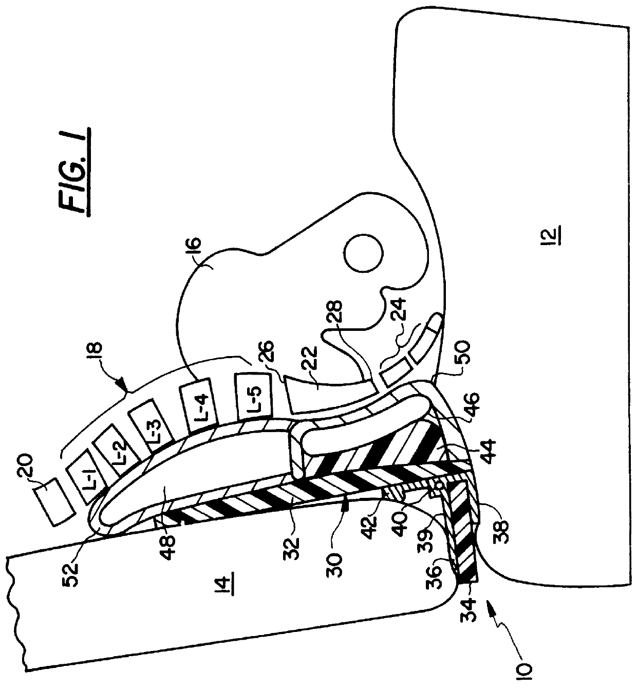
With reference to FIG. 1, one embodiment of the present invention is shown in cross-section, and generally indicated at 10. The device 10 is shown being used between a seat bottom 12 and a seat back 14, with only portions of the seat structure being shown.

In order to correlate the present invention and its effect on certain anatomical components of a person's body, FIG. 1 includes the pelvis 16, the five lumbar vertebrae, generally indicated at 18, with the vertebras specifically referenced as L1-L5, respectively. A first and lowermost thoracic vertebrae is shown at 20. The sacrum is shown at 22 and the upper one third is the region or area called the sacral base is below vertebra L-5. Below sacrum 22 is the coccyx 24, which is comprised of a series of smaller bones that, as a group, tend to curve in an anterior direction. In older adults the smaller coccyx bones can actually fuse together and are considered to be a part of the sacrum.

As noted, the sacrum 22 includes a sacral base o...


PUM


Abstract

A spinal support device for applying a directed and concentrated force on the sacrum to position the sacrum and pelvis to thereby establish a desired spinal posture when in a seated position. The device provides isolatable force on the sacrum from the sacral base line downwardly to a bottom seat surface and for a width across an individual's back approximately equal to twice the dimension of the posterior portion of the individual's sacrum.

Description

1. Field of the InventionThe present invention relates to an improvement in a back support system that establishes a desired postural position by creating specific sacral pressure and to apparatus that will properly position the sacrum, the pelvis, including the iliac crests, and the supporting neuro-musculo-skeletal system to produce total pelvic stability.2. Description of the Prior ArtBack pain, in concept and in fact, is not only prevalent in society but is an area of much research and patent activity. Back pain is something many individuals experience at work, at home, and during the trip therebetween. Back pain has many causes, but few cures. The latter is not for a want of trying. Rather, patents on a wide variety of back supports or support systems abound.For example, the patents can be generally divided in groups including those relating to seat developments, sacral or lumbosacral braces, fixed cushions or supports, and inflatable devices.The seat development area can be fu...

Claims


Application Information

Patent Timeline
IPC IPC(8): A47C7/40A47C7/42A61G5/10A61G5/00A61G15/00
CPCA47C7/425A61G2005/1091A61G5/1091
Inventor WALKER, BROCK M.TIMM, EDWARD E.
Owner WALKER BROCK M
Why Eureka
Try Eureka