Method and system for high resolution ultrasonic imaging of small defects or anomalies.

a high-resolution, ultrasonic imaging technology, applied in the direction of optical radiation measurement, interferometric spectrometry, instruments, etc., can solve the problems of insufficient detection of small and deep flaws, poor resolution, and similar limitations of laser-ultrasonics to conventional piezoelectric-based ultrasonics

Inactive Publication Date: 2000-10-03
NAT RES COUNCIL OF CANADA
View PDF1 Cites 91 Cited by
  • Summary
  • Abstract
  • Description
  • Claims
  • Application Information

AI Technical Summary

Problems solved by technology

For the detection of small defects, laser-ultrasonics has similar limitations to conventional piezoelectric-based ultrasonics, caused by the wave nature of the interrogation and diffraction effects.
The spatial resolution of laser-ultrasonics depends upon the spot sizes of the generation and detection lasers and may be inadequate for detecting small and deep flaws.
In the opposite case, focusing the laser beam to a small laser spot yields a strongly diverging acoustic wave, leading also to poor resolution.
However the technique described in these two patents presents several difficulties which limit their applicability.
A first difficulty originates from the fact that lasers have usually relatively low repetition rates, usually much lower than piezoelectric transducers, which makes data acquisition time very long, so a way to minimize data acquisition duration while maintaining adequate resolution is desirable.
A second difficulty is the long time taken by SAFT processing with the time domain approach used in these two patents.
This time domain approach, while straightforward in its principle and implementation, is not very efficient and is very computation intensive.
A third difficulty originates from the ultrasonic pulse produced by laser generation.
This pulse has a unipolar shape so it does not provide destructive interference at locations without defects, resulting in a broad background around discontinuities.
Considering that high spatial resolution relates to a short pulse duration (see equation 1) or a large frequency bandwidth, filtering the low frequency components does not appear to be optimal.
Even with improved computation efficiency, the known frequency-domain method does not provide a clue on how to get optimum resolution.
A way to control the aperture size is also missing, which is significant since the strength of the ultrasonic wave and the detection sensitivity both decrease as the lateral distance between the sampling point and the observation point increases and adding contributions from highly offset points contributes more noise than signal.
Also, previous art related to SAFT processing does not teach how to minimize the number of sampling points in order to minimize both data collection and processing durations, while keeping adequate resolution.

Method used


Image

  • Method and system for high resolution ultrasonic imaging of small defects or anomalies.
  • Method and system for high resolution ultrasonic imaging of small defects or anomalies.
  • Method and system for high resolution ultrasonic imaging of small defects or anomalies.

Examples


Embodiment Construction

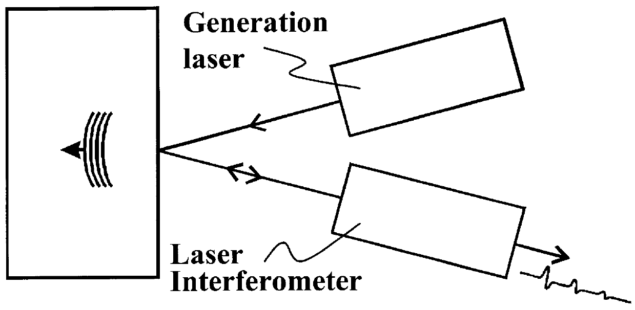
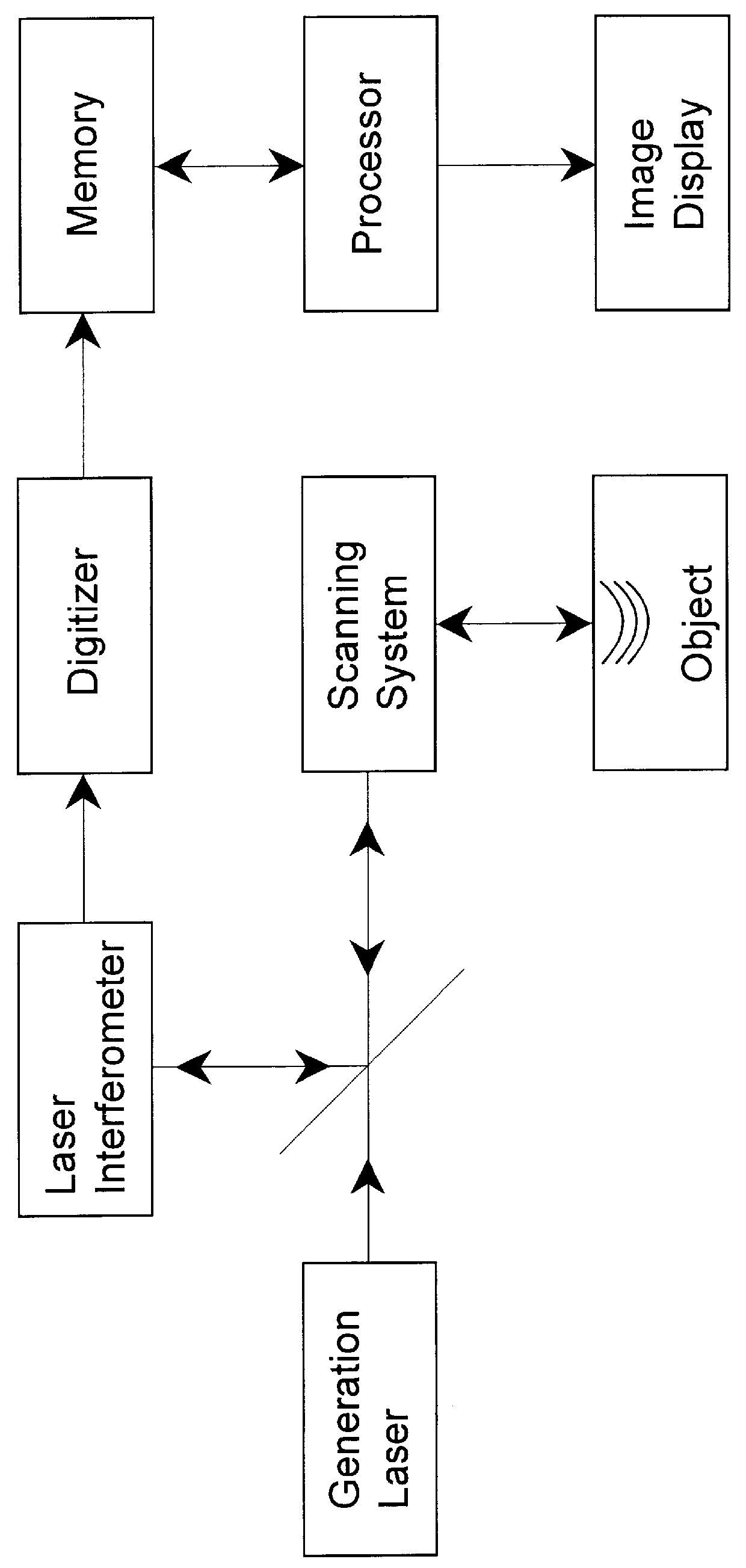
Referring now to FIG. 2a the system according to one preferred embodiment comprises a laser ultrasonic system collecting a 2-D array of ultrasonic signals at the surface of the sample for imaging small defects at its inside. The generation laser 10 is a pulsed laser source and the laser interferometer 12 for detecting backscattered ultrasound comprises a long pulse laser or continuous laser coupled to an optical interferometer. The two laser beams for generation and detection, are focused at the same location onto the surface in a manner similar to the arrangement shown in FIG. 1b. A scanning system 14 is employed for generating and detecting ultrasound at a plurality of scanning positions constituting the measurement grid at the surface of the object 16. In the present embodiment, the array of signals is obtained by scanning the beams on the sample surface with steered mirrors. Alternatively, the sample could be moved using an X-Y translation table. Preferably, the measurement grid...


PUM

PropertyMeasurementUnit
total opening angleaaaaaaaaaa
diameteraaaaaaaaaa
diameteraaaaaaaaaa

Abstract

A method and system is provided for enhanced ultrasonic detection and imaging of small defects inside or at the surface of an object. The Synthetic Aperture Focusing Technique (SAFT) has been used to improve the detectability and to enhance images in conventional ultrasonics and this method has recently been adapted to laser-ultrasonics. In the present invention, an improved version of the frequency-domain SAFT (F-SAFT) based on the angular spectrum approach is described. The method proposed includes temporal deconvolution of the waveform data to enhance both axial and lateral resolutions, control of the aperture and of the frequency bandwidth to improve signal-to-noise ratio, as well as spatial interpolation of the subsurface images. All the above operations are well adapted to the frequency domain calculations and embedded in the F-SAFT data processing. The aperture control and the spatial interpolation allow also a reduction of sampling requirements to further decrease both inspection and processing times. This method is of particular interest when ultrasound is generated by a laser and detected by either a contact ultrasonic transducer or a laser interferometer.

Description

1. Field of the InventionThis invention relates to a method and a system for ultrasonic detection and imaging of small defects inside or at the surface of an object by an improved version of the Synthetic Aperture Focusing Technique, and particularly to such method where ultrasound is generated by a laser and detected by either a contact ultrasonic transducer or a laser interferometer.2. Description of Prior ArtUltrasound is a well-recognized technique for finding defects or discontinuities in objects. Ultrasound provides not only information on the presence of such discontinuities, but also an indication on their depth, deduced from the arrival time of the echoes and the knowledge of the elastic wave velocity. By scanning the surface with a piezoelectric transducer, the object can be mapped out throughout its entire volume and the information displayed as B-scans or C-scans. B-scans are planar cuts through the material and indicate directly the depth of the discontinuities that are...

Claims


Application Information

Patent Timeline
Patent Type & Authority Patents(United States)
IPC IPC(8): G01N29/44G01N29/40G01N29/24G01N29/46G01N29/36G01N29/42G01S15/89G01S15/00
CPCG01N29/069G01N29/2418G01N29/40G01N29/42G01S15/8997G01N29/46G01N2291/015G01N2291/0422G01N2291/0423G01N2291/0427
Inventor LEVESQUE, DANIELBLOUIN, ALAINNERON, CHRISTIANMONCHALIN, JEAN-PIERRE
Owner NAT RES COUNCIL OF CANADA
Why Eureka
Try Eureka