Flat servo bursts for arcuate track scanner

a technology of arcuate track and servo control, which is applied in the direction of maintaining head carrier alignment, recording signal processing, instruments, etc., can solve the problems of adding to the complexity and expense of scanner electronics, difficulty in aligning the head with the data tracks during a subsequent read operation, and type of servo control

Inactive Publication Date: 2000-10-10
CERTANCE
View PDF29 Cites 28 Cited by
  • Summary
  • Abstract
  • Description
  • Claims
  • Application Information

AI Technical Summary

Problems solved by technology

For example, if there is some vibration of a scanner during the writing operation, it may be difficult to align the head with the data tracks during a subsequent read operation, particularly if the read operation is performed by a different scanner.
In practice, however, there are certain problems with that type of servo control.
The detection of the servo burst signals requires two different frequency filters, one for each servo frequency, adding to the complexity and expense of the scanner electronics.
Inadequate filtering causes distortions of the relative amplitudes of the detected servo bursts.
Any distortion of the relative amplitudes may introduce inaccuracies in the position control error signal and the tracking in response to that signal.
As shown by the above discussion, the analog processing circuitry required to detect the two servo bursts is overly complex, and the use of two separate servo burst frequencies simultaneously detected through one servo head may cause problems in accurately detecting the amplitude relationship and thus inaccuracies in positioning of the scanner head assembly relative to the tracks containing the two servo bursts.
However, the proposed solutions did not address the problem of the size of the servo regions.
As shown in FIG. 11, however, a problem still arises relating to the size of the servo regions, particularly in the regions where the servo signals have an azimuth at an angle to the longitudinal axis of the tape. FIG. 11 is an enlarged view of several tracks recorded in the format of FIG. 10 and showing the azimuthal orientation of the recorded information.

Method used


Image

  • Flat servo bursts for arcuate track scanner
  • Flat servo bursts for arcuate track scanner
  • Flat servo bursts for arcuate track scanner

Examples


first embodiment

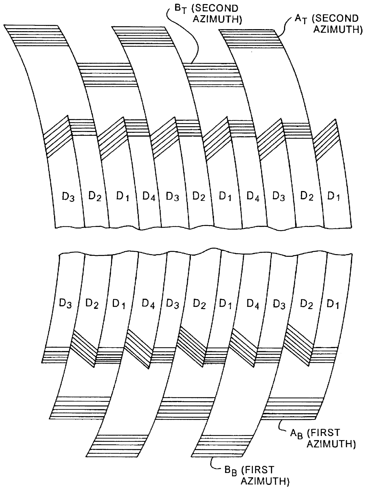
In accord with the first embodiment, all write and read heads perform both data related operations and servo related operations. For the servo operations, however, each head operates in only one servo region, i.e. the region in which the head azimuth is substantially parallel to the longitudinal tape axis. No one head writes servo bursts in both the top and bottom regions.

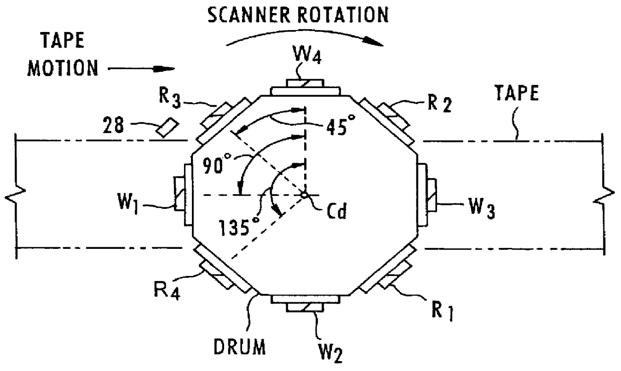
The first write head W.sub.1 writes a data track D.sub.1 and a lower region servo burst A.sub.B. The second write head W.sub.2 writes an upper region servo burst A.sub.T and a data track D.sub.2. The third write head W.sub.3 writes a data track D.sub.3 and a lower region servo burst B.sub.B. The fourth write head W.sub.4 writes an upper region servo burst B.sub.T and a data track D.sub.4. This sequence of write operations repeats along the length of the tape. These write operations are discussed in more detail below with regard to FIGS. 4A to 4D.

As noted, the bursts A.sub.T and B.sub.T in the top servo region are w...

second embodiment

In a second embodiment, the scanner system records servo bursts only in the lower servo region. The upper servo region is eliminated entirely, providing a still further increase in the amount of tape real estate available for recording user data. The write heads W.sub.1 and W.sub.3 write data followed by servo signals A.sub.B and B.sub.B, and the read heads R.sub.1 and R.sub.3 read data and the servo signals A.sub.B and B.sub.B. However, the write heads W.sub.2 and W.sub.4 only write data, and the read heads R.sub.1 and R.sub.3 read data only data.

In the second embodiment, servo control of the tape speed is based on the timed sampling of the bottom servo signals sensed by read heads R.sub.1 and R.sub.3, in essentially the same manner as in the earlier embodiment. However, the tilt angle control is based on an envelope detection of the data tracks. When the ASHA is properly centered, the envelope of the data track signal from the operative read head is relatively constant. By contras...


PUM

PropertyMeasurementUnit
distanceaaaaaaaaaa
chord lengthaaaaaaaaaa
lateral distanceaaaaaaaaaa

Abstract

To control operations of an arcuate scanning head assembly, servo signals are written in one or more designated servo regions along a recording tape, for example along one or both edges of the recording area on the tape. To minimize the space occupied by the servo signals, the servo signals are always written with an azimuth that is substantially parallel to the longitudinal axis of the tape. In the preferred embodiment, servo signals aligned with adjacent tracks are written at two different positions within a servo region. As a read head passes over a track and the servo region, the head should overlap the servo signal aligned with that track and a portion of the servo signal aligned with the adjacent track. A control system samples the signal from the read head in a first time window corresponding to passage of the head across a burst aligned with the track and in a second time window corresponding to passage of the head across a burst aligned with the adjacent track. The system controls one or more parameters relating to the scanning operation as a function of a relationship of the two sampled amplitudes.

Description

The present invention relates to tape drives having an arcuate scanner, and more particularly to information formats and servo control techniques of the scanner heads based on signals within the information format, to accurately control the arcuate scanner during reading and writing operations.DESCRIPTION OF RELATED ARTA number of magnetic tape drive systems have been developed to provide mass data storage, for example for personal computer systems. One emerging technology providing high density storage, preferably on quarter inch magnetic tape, utilizes arcuate scanning. With this type of scanning, read and write scanner heads are mounted near the periphery of a circular planar surface and rotated thereon about an axis passing through the center of the circular surface and through the plane of a longitudinally-moving tape. In writing data on a tape, arcuate scanners produce a sequence of arcuately-shaped tracks which are transverse to the longitudinal axis of the tape.Examples of a...

Claims


Application Information

Patent Timeline
Patent Type & Authority Patents(United States)
IPC IPC(8): G11B21/16G11B15/12G11B21/24G11B21/04G11B5/588G11B15/467G11B21/08G11B5/53
CPCG11B5/588G11B15/125G11B21/24G11B21/04G11B15/4677G11B5/537G11B21/086
Inventor GOKER, TURGUY
Owner CERTANCE
Why Eureka
Try Eureka