Method and apparatus for producing superheated steam using heat from the incineration of waste material

a waste material and superheated steam technology, which is applied in lighting and heating apparatus, combustion types, furnaces, etc., can solve the problems of reducing the generating efficiency of prior art garbage incinerators, reducing the efficiency of waste heat generation, and increasing the risk of corrosion

Inactive Publication Date: 2000-10-17
MITSUBISHI HEAVY IND LTD
View PDF4 Cites 67 Cited by
  • Summary
  • Abstract
  • Description
  • Claims
  • Application Information

AI Technical Summary

Problems solved by technology

At temperatures above 350.degree. C., as the surface temperature of the tubes increases, the corrosion becomes extremely serious.
This limited the temperature of the steam which could be produced to approximately 300.degree. C.
As a result, the generating efficiency of prior art garbage incinerators was below 15%.
This arrangement will yield a large quantity of superheated steam.
If the char were allowed to flow untreated into a discharge line made of common refractory materials, the line would not be able to sustain withstand the heat.
Controlling the volume of the fluidized bed medium which is to be recirculated is thus an extremely complex problem.
For this reason it is not possible to pre...

Method used


Image

  • Method and apparatus for producing superheated steam using heat from the incineration of waste material
  • Method and apparatus for producing superheated steam using heat from the incineration of waste material
  • Method and apparatus for producing superheated steam using heat from the incineration of waste material

Examples


Embodiment Construction

In this section we shall explain in detail, with reference to the drawings, several preferred embodiments of this invention. Insofar as the dimensions, material, shape and relative position of the structural components which figure in the embodiments are not specifically disclosed, the scope of the invention is not limited to those shown. The embodiments are meant to serve merely as illustrative examples.

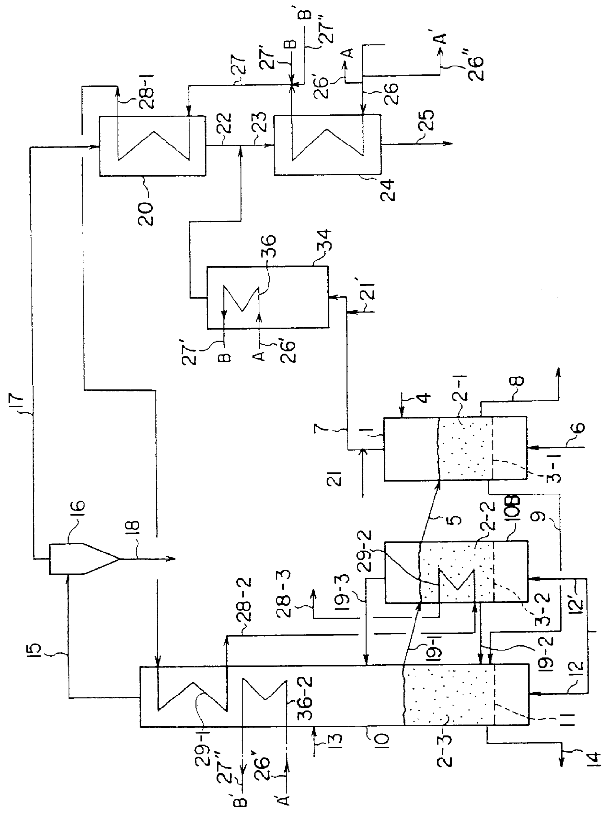
FIG. 1 shows an apparatus for producing superheated steam using the heat from incineration of waste materials which is a first preferred embodiment of the present invention. In this figure, 1 is a pyrolysis furnace comprising a fluidized bed; the fluidized bed medium 2-1, namely, fluidized sand or a similar material, is supplied onto dispersion plate 3-1, which is a perforated plate or the like. The garbage or other waste material enters the system via supply line 4, and the fluidized sand via circulation (or return) line 5. The combustion exhaust gas supplied via input line 6 creat...


PUM


Abstract

PCT No. PCT/JP97/00573 Sec. 371 Date Jan. 12, 1998 Sec. 102(e) Date Jan. 12, 1998 PCT Filed Feb. 27, 1997 PCT Pub. No. WO97/32161 PCT Pub. Date Sep. 4, 1997According to the present invention, boiler water is pressurized so that its boiling point is set at approximately 200 DEG C. to 320 DEG C. The boiler water is heated in at least two stages. Thermal energy of gases containing chlorine compounds is used to heat the water to its boiling point. Thermal energy of gases which do not contain chlorine compounds is used to heat the water from its boiling point until superheated steam of a given temperature is generated. The heating which uses the thermal energy of gases containing chlorine compounds is accomplished using the thermal energy from the combustion of pyrolysis gases obtained from a pyrolysis means in which waste material is supplied into a chamber containing a fluidized bed medium which has been heated to at least 300 DEG C., and a pyrolytic reaction is induced. The heating which uses the thermal energy of gases which do not contain chlorine compounds is accomplished using the thermal energy obtained from a char combustion means to combust char in which a char mixture consisting of unpyrolyzed residue and fluidized bed medium removed from the pyrolysis means is fluidized by a stream of air, and the unpyrolyzed residue is combusted.

Description

This invention concerns a superheated steam generator which employs incinerating municipal garbage or industrial waste, and produces superheated steam with the heat energy from such an incineration. The superheated steam produced by this apparatus might, for example, be used for an electric power plant. The heat energy of the incineration can also be used to melt the ash resulting from incineration so that it can be used again as a resource.TECHNICAL BACKGROUNDIn the prior art, apparatuses to incinerate waste such as municipal garbage have frequently employed fluidized beds. Such apparatuses blow air or the exhaust gas from incineration into the fluidized bed medium, which may be sand, from below a dispersion plate (e.g., a perforated plate) in the furnace onto which the sand is supplied. The material is heated and thereby fluidized. Waste such as municipal garbage is fed into the fluidized bed formed in this way and combusted.The gases generated by this incineration are exhausted t...

Claims


Application Information

Patent Timeline
IPC IPC(8): F23G5/027F23G5/46F22B31/00F22B31/04F23G5/30
CPCF22B31/045F23G5/027F23G5/30F23G5/46Y10S423/18F23G2201/304Y02E20/12Y10S588/90F23G2201/303F22G1/16
Inventor HORIZOE, HIROTOSHISHIMIZU, YOSHIHITOSATO, JUNYASUDA, SHIZUOKAIHARA, YUJIKAWAMI, YOSHIMASA
Owner MITSUBISHI HEAVY IND LTD
Why Eureka
Try Eureka