Method and apparatus for a filler valve

a filler valve and valve body technology, applied in the field of filler valves, can solve the problems of not being able to efficiently operate in non-carbonated systems, the rotating valve of the justis '589 device is quite complex, and the franz '591 cannot provide a mechanism that can fill at higher flow rates, etc., to achieve efficient operation, high flow rate, and convenient use

Inactive Publication Date: 2000-10-24
KIHOLM INDS
View PDF16 Cites 20 Cited by
  • Summary
  • Abstract
  • Description
  • Claims
  • Application Information

AI Technical Summary

Benefits of technology

In another preferred embodiment of the invention, the slider and the filler stem can include tapered lengths to allow the filler valve to easily be employed for containers having smaller necks.
According to one advantage of the invention, the filler valve provides a mechanism that can fill at high flow rates.
According to another advantage of the invention, the filler valve efficiently operates in non-carbonated liquid filling systems and can readily ret...

Problems solved by technology

A problem with Franz '591 is that it relies on gravity flow to fill the bottle, after the air pressure with the bottle equalized with the air reservoir above the filling liquid.
Franz '591 fails to provide a mechanism that can fill at higher flow rates.
Carbonated liquid filling mechanisms, though showing aspects potentially applicable to noncarbonated liquid filing mechanisms, typically all fail to efficiently operate in non-carbonated systems.
This rotating valve of the Justis '589 device is quite complex and includes bottle pressurization features that are not required in non-carbonated filling systems.
However, the Yun '873 valve system includes a complex array of bias springs that together operate to control the action of the valve.
Yun '873 fails to provide an easily adjustable valve with the ability to easily fine tune and adjust the actions of the valve.
Yun '058 also includes a central vent tube that is utilized with a concentric liquid filling valve, but again, as with Yun '873, fails to pr...

Method used


Image

  • Method and apparatus for a filler valve
  • Method and apparatus for a filler valve
  • Method and apparatus for a filler valve

Examples


Embodiment Construction

The present invention comprises a filler valve that is specially configured for attachment onto a conventional, high speed, fluid container filling system. As compared to conventional filling valves assemblies, the filler valve of the present invention includes novel features that result in a greater reliability in operation, increased operational speeds, and easier adjustments in operational parameters.

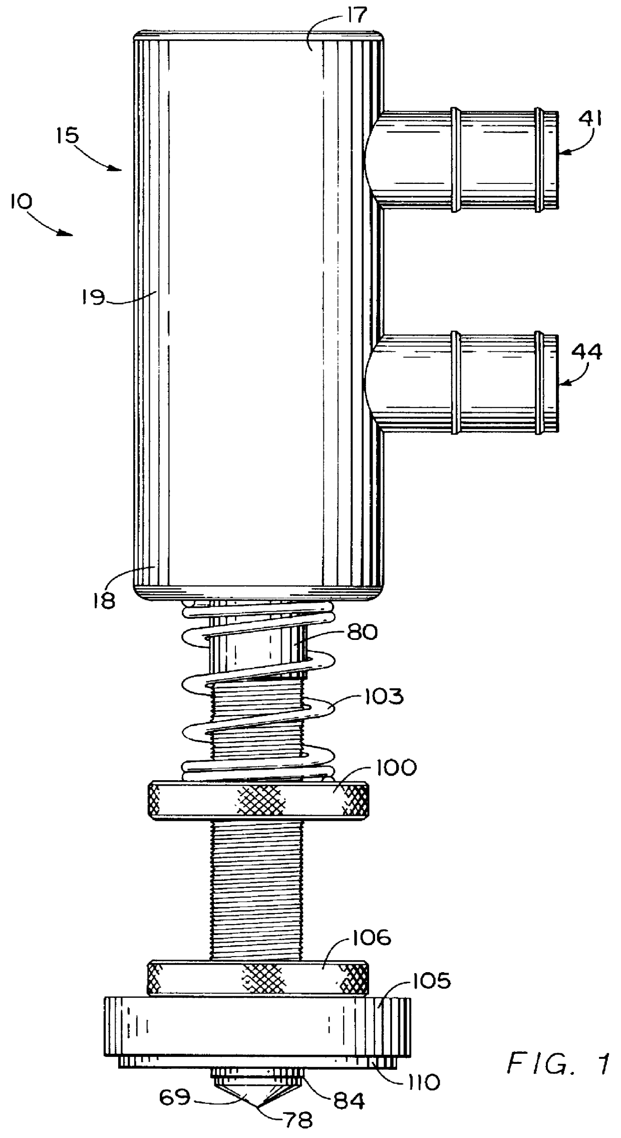
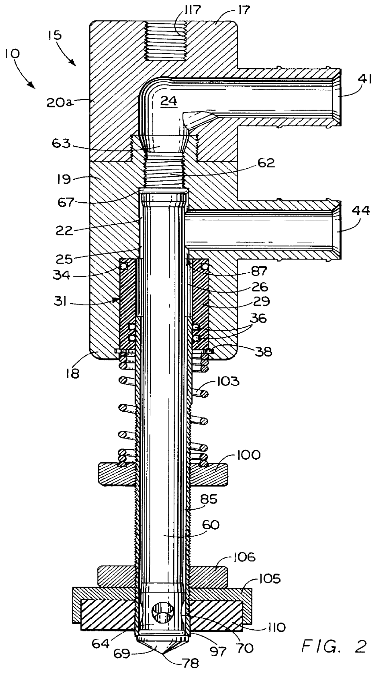
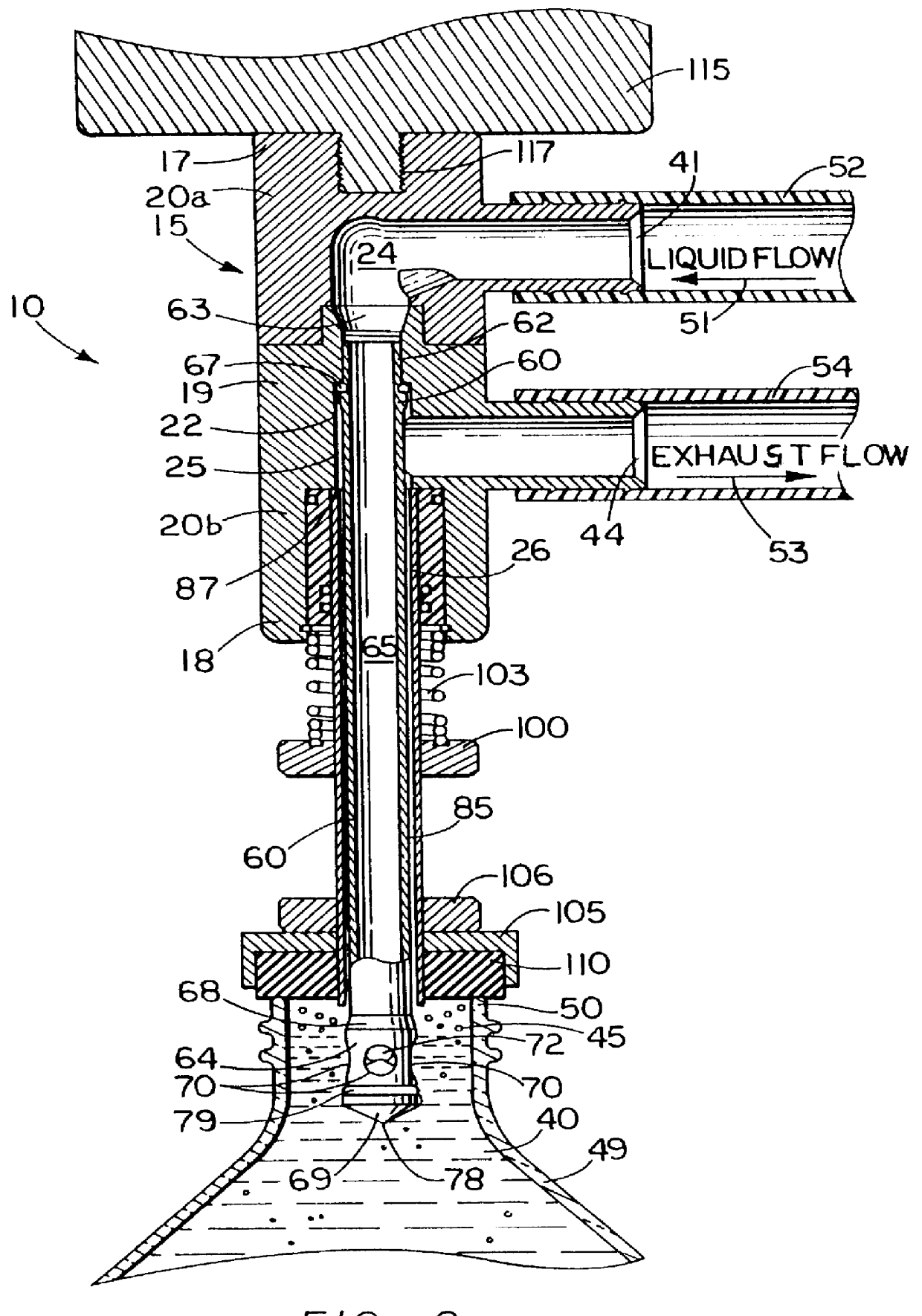
FIGS. 1 through 3 show a filler valve 10, according to a preferred embodiment of the present invention. The filler valve includes a manifold 15 having a top end 17, a base end 18 and a middle portion 19, located between the top end and the base end. The manifold is preferably formed from a metal stock that is machine tooled to the desired dimensions. The manifold, as well as all metal components of the filling valve, are most preferably manufactured from a stainless steel. Most preferably, ANSI 316 (UNS S31600) stainless steel alloy is employed throughout. 316 stainless is most prefe...


PUM

PropertyMeasurementUnit
Lengthaaaaaaaaaa
Speedaaaaaaaaaa

Abstract

An improved filling valve specially configured for attachment onto a conventional, high speed liquid filling machine that is typically utilized in food product container packaging lines to quickly fill large numbers of containers, such as bottle or cans. A filler valve has several improvements that result in greater reliability in operation, increased operational speed, and easier adjustment in operational parameters. The filler valve including a manifold that receives a manifold insert and a spring nut that abuts to a slider. The slider is the only moving part of the filler valve. A filler stem is received through the slider and attaches to the manifold. For filling, the top opening of a bottle is placed against a spanner nut and the manifold lowered, thereby compressing the slider into the manifold to insert the stem into the container. A liquid is then injected into the container, while displaced air is exhausted into the co-axial annular space between the stem and the slider. The stem also preferably contains four outlet ports.

Description

The invention relates to a method and apparatus for filling valves for use in container filling machines and more particularly to a filler valves specially configured for attachment onto conventional, high speed, container fluid filling systems.Container filling machines are widely utilized in food product container packaging lines to quickly fill large numbers of containers. The efficient and reliable operation of the filling valves of these filling machines is critical to the process. Historically, the quick and economical filling of containers has been an object of a large number of devices. Container filling machines have evolved over the years from simple mechanisms to complex devices, yet with many features evolving and improving over time.An example of an early device with advanced features is the U.S. Pat. No. 2,671,591 to Franz. Franz '591 discloses a mechanism for filling containers with a liquid, such as milk. The Franz '591 apparatus includes a central exhaust passage wi...

Claims


Application Information

Patent Timeline
IPC IPC(8): B67C3/02B67C3/26
CPCB67C3/2637
Inventor KIHOLM, ROBERT
Owner KIHOLM INDS
Why Eureka
Try Eureka