Tube and shell reactor with oxygen selective ion transport ceramic reaction tubes

a technology of ceramic reaction tubes and oxygen selective ions, which is applied in the direction of gas-gas reaction processes, physical/chemical process catalysts, separation processes, etc., can solve the problems of difficult economic transportation of natural gas and methane, high maintenance costs of steam reforming reaction and partial oxidation reaction, and difficult conversion into liquid fuels. , to achieve the effect of increasing the oxygen flux, increasing the driving force of oxygen transport, and reducing the partial oxygen pressure of the anode sid

Inactive Publication Date: 2000-10-31
STANDARD OIL CO +1
View PDF27 Cites 155 Cited by
  • Summary
  • Abstract
  • Description
  • Claims
  • Application Information

AI Technical Summary

Benefits of technology

FIG. 9 illustrates an embodiment in which a product stream is recycled with the first process gas 88 to increase the oxygen flux and therefore heat generation, since the recycled product gas contains carbon monoxide and hydrogen and the reaction of these gases with the permeating oxygen is faster. This results in decreasing the anode side partial oxygen pressure and increasing the oxygen transport driving force. Oxygen flux depends on the rate of oxygen transport from t

Problems solved by technology

Natural gas and methane, a major constituent of natural gas, are difficult to economically transport and are not easily converted into liquid fuels, such as methanol, formaldehyde and olefins, that are more readily contained and transported.
Both the steam reforming reaction a

Method used


Image

  • Tube and shell reactor with oxygen selective ion transport ceramic reaction tubes
  • Tube and shell reactor with oxygen selective ion transport ceramic reaction tubes
  • Tube and shell reactor with oxygen selective ion transport ceramic reaction tubes

Examples


Embodiment Construction

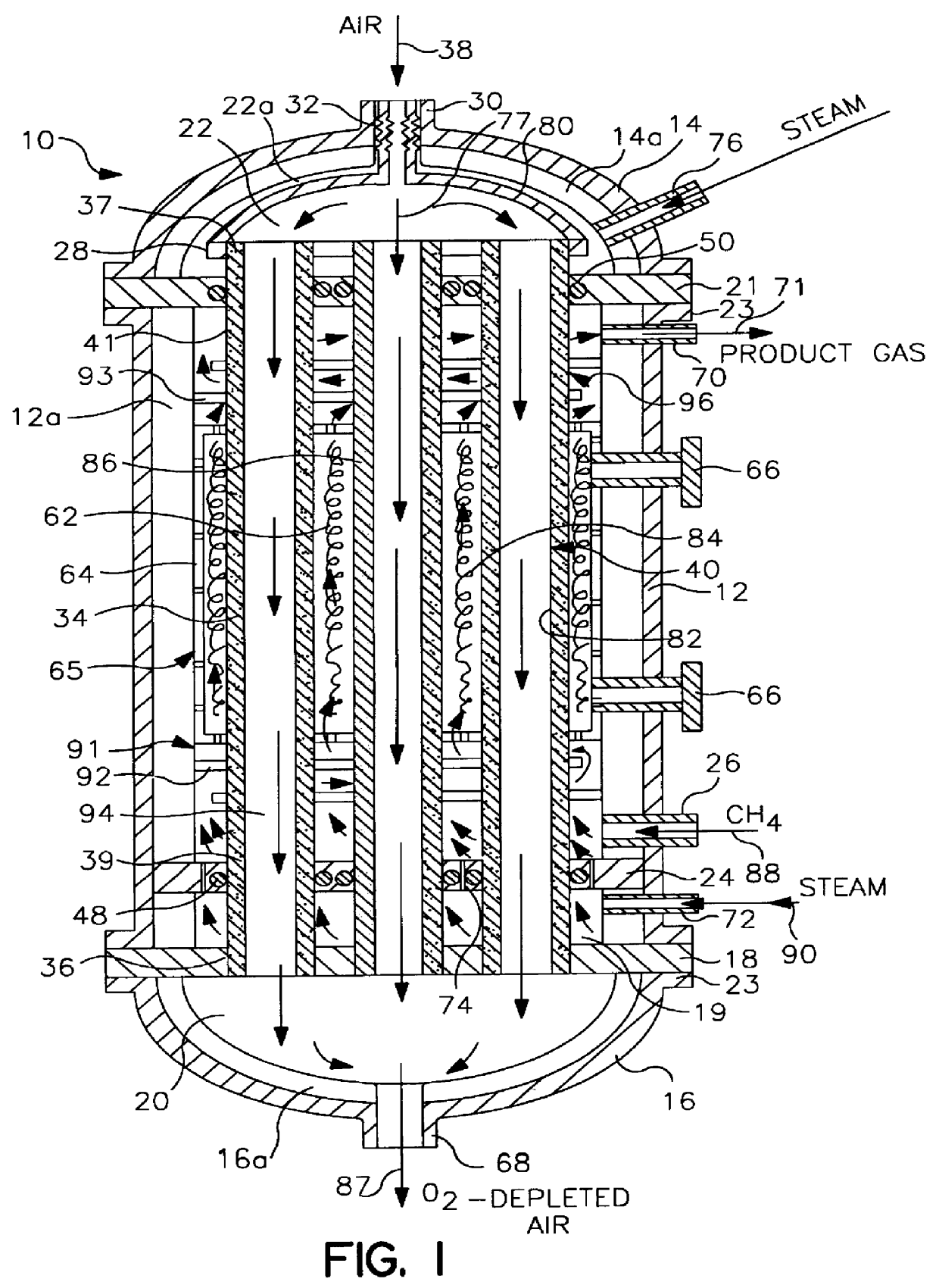
tube and shell reactor of the type illustrated in FIG. 1 was computer modeled. The reactor had 1,000 reaction tubes 34 with each reaction tube having a length of 31 feet. Of this length, the reaction section 65 had a length of 18 feet, the pre-heat section 91 had a length of 6 feet and the cooling section 96 had a length of 7 feet. The tube to tube pitch was 1.5" and the tube bundle diameter was 4 feet. Each tube was formed from a dense mixed conductor that was capable of selective ion transport in the reaction section 65 and was inactive outside the reaction section 65. The tubes had an outside diameter of 1 inch and an inside diameter of 0.875 inch. The membranes 40 in the reaction section 65 were formed from LaSrFeCr perovskite.

FIG. 13 graphically illustrates the gaseous composition of the reactor. The horizontal axis represents the percent of the reaction section that has been traversed by the reaction constituents while the vertical axis identifies the molar percent of each con...


PUM

PropertyMeasurementUnit
Temperatureaaaaaaaaaa
Pressureaaaaaaaaaa
Diameteraaaaaaaaaa

Abstract

A reactor comprising: a hollow shell defining a hermetic enclosure; a plurality of tube sheets disposed within said hermetic enclosure, a first one of said plurality of tube sheets defining a first chamber; at least one reaction tube each having a first end and an opposing second end, said first end being fixedly attached and substantially hermetically sealed to one end of said plurality of tube sheets and opening into said first chamber, the second end being axially unrestrained; each of said reaction tubes is comprised of an oxygen selective ion transport membrane with an anode side wherein said oxygen selective ion transport membrane is formed from a mixed conductor metal oxide that is effective for the transport of elemental oxygen at elevated temperatures and at least a portion of said first and second heat transfer sections are formed of metal; each of said reaction tubes includes first and second heat transfer sections and a reaction section, said reaction section disposed between said first and second heat transfer sections; a reforming catalyst disposed about said anode side of said oxygen selective ion transport membrane; a first process gas inlet; a second process gas inlet; and, a plurality of outlets.

Description

The invention relates to a process for producing a product gas, such as syngas or an unsaturated hydrocarbon, utilizing a combination of an exothermic partial oxidation reaction and an endothermic steam reforming reaction. More particularly, the oxygen for the exothermic reaction is received by transport through an oxygen selective ion transport membrane element, and the heat generated by the exothermic reaction is supplied to the endothermic reaction.Natural gas and methane, a major constituent of natural gas, are difficult to economically transport and are not easily converted into liquid fuels, such as methanol, formaldehyde and olefins, that are more readily contained and transported. To facilitate transport, methane is typically converted to synthesis gas (syngas) which is an intermediate in the conversion of methane to liquid fuels. Syngas is a mixture of hydrogen and carbon monoxide with H.sub.2 / CO molar ratio from about 0.6 to about 6.One method to convert methane to syngas...

Claims


Application Information

Patent Timeline
IPC IPC(8): B01J8/00B01J19/24B01J12/00C01B3/00C01B3/38C01B13/02B01J8/06C01B3/24C25B13/08
CPCB01J8/009B01J19/2425B01J19/2475C01B3/382C01B3/384C01B13/0251B01J12/007C01B2210/0046B01J2208/00309B01J2208/00477B01J2208/00495B01J2208/0053B01J2208/00539B01J2208/00548B01J2208/00628B01J2219/00117B01J2219/00155B01J2219/00159B01J2219/00162B01J2219/00186B01J2219/00777C01B2203/0233C01B2203/066C01B2203/0811C01B2203/141C01B2203/142C01B2203/148C01B2203/82Y02P20/129C01B3/24
Inventor GOTTZMANN, CHRISTIAN FRIEDRICHPRASAD, RAVISCHWARTZ, JOSEPH MICHAELBERGSTEN, VICTOR EMMANUELWHITE, JAMES ERICMAZANEC, TERRY J.CABLE, THOMAS L.FAGLEY, JOHN C.
Owner STANDARD OIL CO
Why Eureka
Try Eureka