Low wattage, high flow electrical control valve

a technology of electrical control valves and low wattage, which is applied in the direction of valve housings, operating means/releasing devices, valves, etc., can solve the problems of not being able to apply all the brakes in the train, and affecting the operation of the valv

Inactive Publication Date: 2000-11-07
WESTINGHOUSE AIR BRAKE CO
View PDF5 Cites 16 Cited by
  • Summary
  • Abstract
  • Description
  • Claims
  • Application Information

AI Technical Summary

Benefits of technology

It is, therefore, one of the primary objects of the present invention to provide a fluid flow control valve assembly which may be both opened or closed by a relatively low wattage electrical signal.

Problems solved by technology

Second, when a brake application is required, air is vented from the brake pipe air line through a valve located in the lead locomotive.
For one thing, the time required for a pressure decrement to propagate down the line of cars in a long freight train is relatively long.
Hence, when a brake application is required, it takes some time before all of the brakes in the train are applied.
There are also some operational difficulties due to the fact that the same compressed air line is used both for charging the air reservoirs in the cars and for signalling a brake application.
When a brake application is made, some of the air in the air reservoirs in the cars is depleted.
Since the pressure in the brake pipe air line has been reduced to signal the brake application, there is not sufficient air pressure in the brake pipe air line to recharge the air in the reservoirs.
Another restriction of conventional pneumatic brakes designed for use on very long trains is that they must be of the direct release type.
This is a case in which an engineer, upon starting to descend a grade, makes a brake application which is too heavy for a section of the grade, so that the train does not maintain its preferred speed.
The radio approach may have difficulty due to terrain which intervenes between the locomotive and the remote receiver causing the remote unit to fail to dump brake pipe pressure.
However, the operational difficulty of not being able to partially or gradually reduce a brake application which is in force is not solved by shortening the time needed for brake pipe pressure to drop.

Method used


Image

  • Low wattage, high flow electrical control valve
  • Low wattage, high flow electrical control valve
  • Low wattage, high flow electrical control valve

Examples


Embodiment Construction

, particularly, when the detailed description is taken in conjunction with the attached drawing figures and with the appended claims.

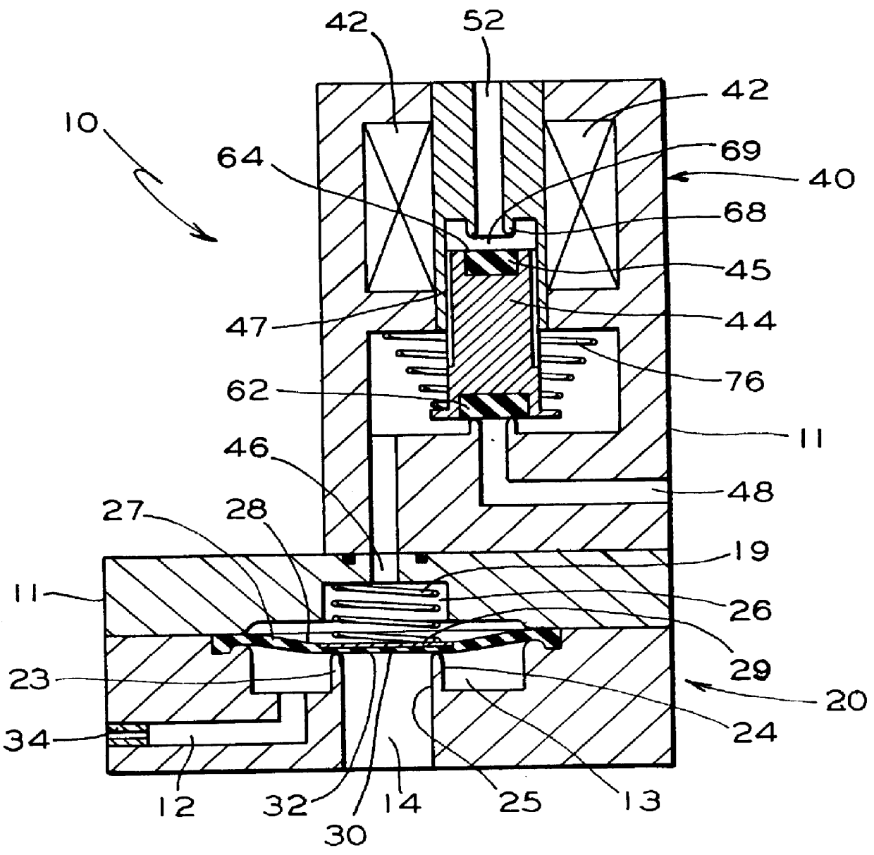
FIG. 1 is a cross-sectional view which shows one presently preferred embodiment of a pressure application valve assembly according to the present invention in a deenergized, closed configuration.

FIG. 2 is a cross-sectional view which shows the pressure application valve assembly, illustrated in FIG. 1, in an energized, open position for applying pressure.

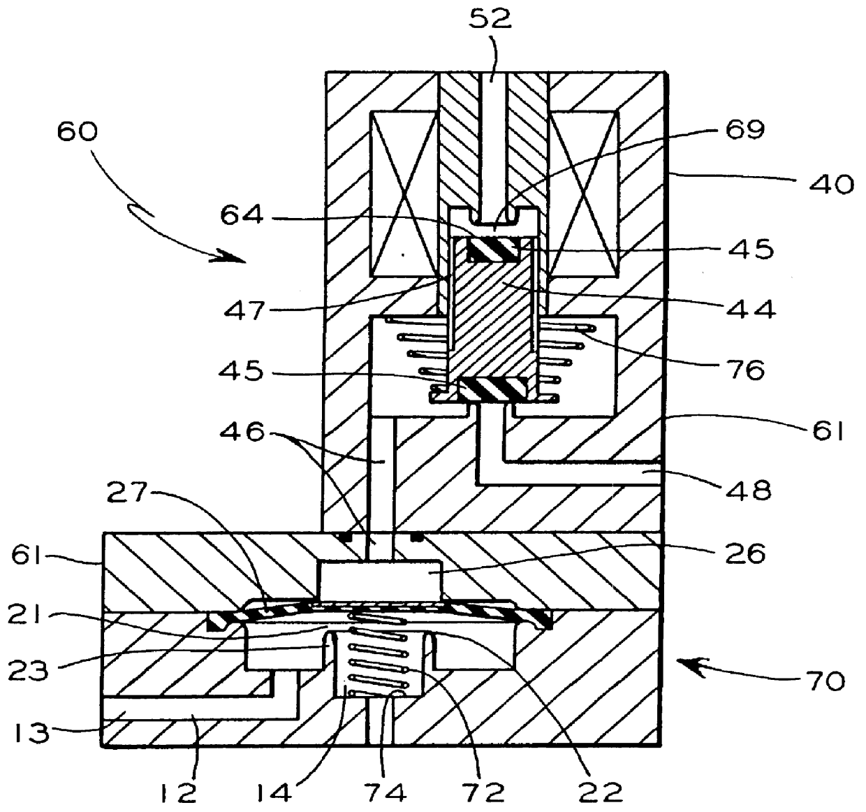
FIG. 3 is a cross-sectional view which shows one presently preferred embodiment of a pressure release valve assembly according to the present invention in a deenergized, open position for releasing pressure.

FIG. 4 is a cross-sectional view which shows the pressure release valve assembly, illustrated in FIG. 3, in an energized, closed position.

FIG. 5 illustrates a flow barrier and its sealing surface used in the valve assemblies illustrated in FIGS. 1-4.

FIG. 6 illustrates an emergency brake application ...


PUM


Abstract

The invention provides an electrically activated valve assembly for control of a fluid. It has a diaphragm with a control chamber on one side and a flow barrier on the second side. Portions of a first flow passage and a second flow passage are on the second side of the diaphragm, with the flow barrier between them. When the control chamber has a relatively high pressure, the diaphragm is pressed against the flow barrier, isolating the first flow passage from the second flow passage. When the control chamber has a relatively low pressure, the diaphragm moves away from the flow barrier, so flow may occur between the first flow passage and the second flow passage. The position of the diaphragm is determined by pressure in the control chamber so the pressure in the control chamber controls the fluid flow connection between the first flow passage and the second flow passage. The valve also has an electrically activated valve responsive to an electrical signal to control pressure in a flow passageway to the control chamber so that when the electrically activated valve is energized, the control pressure is changed, so the electrically activated valve controls the fluid flow connection between the first flow passage and the second flow passage.

Description

The present invention relates, in general, to brake systems which utilize both fluid and electrical signals and, more particularly, this invention relates to a low wattage, high flow electrical control valve for use in an electro-pneumatic railway brake control system.In the conventional railroad air brake system, as developed from the Westinghouse air brake, there is a brake pipe air line which passes from the lead locomotive and from vehicle to vehicle down the length of the train consist and provides two basic functions.First, air from the brake pipe is used to charge compressed air reservoirs disposed on each of the railroad cars. The air stored in these reservoirs provides the energy needed to apply the brake shoes when a brake application is required. When the train is running normally, and no brake application is needed, a high pressure, typically about 90 psi for freight trains and about 110 psi for passenger trains, exists in the brake air line. The reservoirs on the cars a...

Claims


Application Information

Patent Timeline
Patent Type & Authority Patents(United States)
IPC IPC(8): B60T15/00B60T13/66B60T15/02F16K31/36F16K31/40F16K27/00
CPCB60T13/665F16K31/402F16K27/003B60T15/027
Inventor CARROLL, JOHN B.
Owner WESTINGHOUSE AIR BRAKE CO
Why Eureka
Try Eureka