Flush toilet

a technology for flushing toilets and toilets, applied in the field of flushing toilets, can solve the problems of difficult cleaning of such sections, difficult to ensure a high level of sanitation, and contaminated areas, and achieve the effect of reducing the pressure of flushing water and shortening the distance of flushing water circulation

Inactive Publication Date: 2000-11-14
TOTO LTD
View PDF7 Cites 125 Cited by
  • Summary
  • Abstract
  • Description
  • Claims
  • Application Information

AI Technical Summary

Benefits of technology

Moreover, the present invention provides a flush toilet which is characterized in that a flush water discharge section is disposed on the interior side of the bowl section and the flush water passage of an overhanging form is disposed in the position opposite to the flush water discharge section. This configuration of the flush toilet according to the present invention can effectively prevent flush water from splashing outside over the main body of the flush toilet, even if the flush water discharged from the flush water discharge section expands and disperses over a wider area as it flows far apart from the flush water discharge section, because the portion of the bowl section having the largest curvature is shaped in an overhanging form.
In addition, the present invention provides a flush toilet which is further characterized in that the flush water discharge section is provided with two flush water discharge holes which are located separately at different positions so as to flush water in opposite directions and that the flush water discharge holes discharge the flush water in opposite directions along the flush water passage. Therefore, the flush toilet according to the present invention can shorten the distance of circulation of the flush water about the bowl section, thereby reducing a pressure of discharging the flush water.
Still further, the present invention provides a flush toilet which is characterized in that a forced flush water discharge outlet is disposed in a position above a drain path inlet disposed at the bottom portion of the bowl section and above the water level near to a water level of the water chamber of the bowl section, thereby enabling the flush water to flow into the drain path inlet from the flush water passage. Therefore, a floating waste product can be discharged by a small amount of the flush water.
Still further, the present invention provides a flush toilet which is characterized in that a flush water jet hole is disposed for jetting flush water toward a drain path inlet disposed at the bottom portion of the bowl section. This configuration of the flush toilet according to the present invention can promote the pressurized drainage of the flush water and waste product into the drain path.
In addition, the present invention provides a method of washing a flush toilet with flush water, in which the flush water is arranged so as for a main stream of the flush water and branched streams branched from the main stream of the flush water to expand and disperse over an entire area of the inner surface section of the bowl section of the flush toilet, without causing any flush water to splash outside over an upper edge portion of the flush toilet.
More specifically, the present invention provides the method for washing the flush toilet with the flush water in which the main stream of the flush water is flown so as to expand and disperse over a substantially entire periphery of the upper edge of the inner wall surface section of the upper edge portion of the flush toilet without causing the flush water to fail to splash outside over the upper edge portion of the flush toilet, the branched stream of the flush water branched from the main stream thereof is guided so as to expand and disperse over the entire area of the inner surface section of the bowl section of the toilet, and the flush water is then led to a drain path inlet. This method can discharge a waste product floating in the water with a small amount of the flush water.

Problems solved by technology

Therefore, it is difficult to coat the lower side surface section of the rim portion 130 and other sections with the glaze so that they are likely to be contaminated with germs or attached with waste product.
Moreover, it is further difficult to clean the such sections because they are formed with depression that cannot be looked easily as a dead angle from the vision of the user.
Therefore, it is difficult to ensure a high level of sanitation.
In addition, the germs or waste product attached thereto cause a source of generating malodor.
Therefore, the steps for manufacturing the such flush toilets become complicated leading to a rise in costs of manufacturing the flush toilets.

Method used


Image

  • Flush toilet
  • Flush toilet
  • Flush toilet

Examples


first embodiment

(First Embodiment)

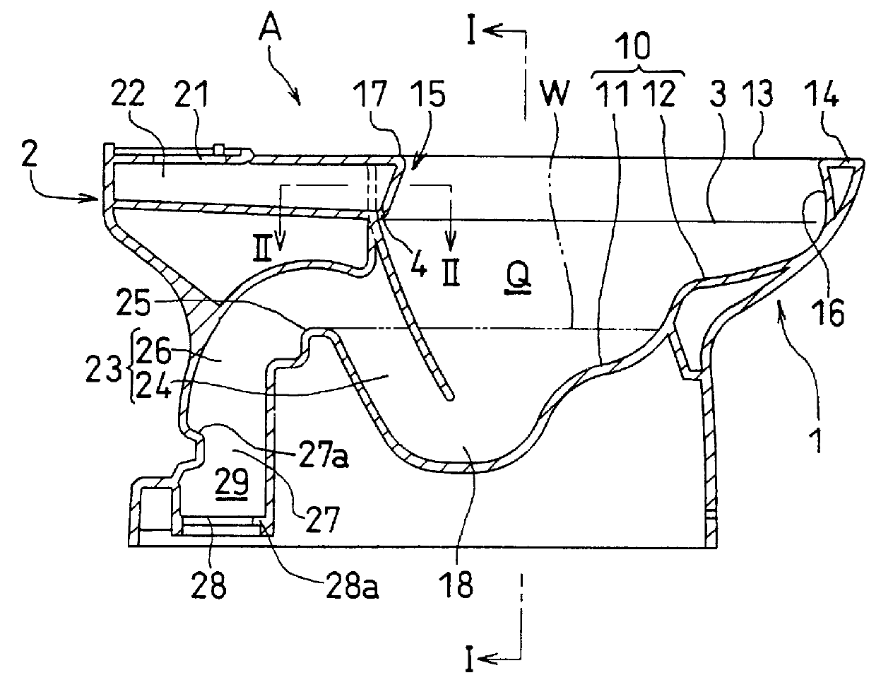
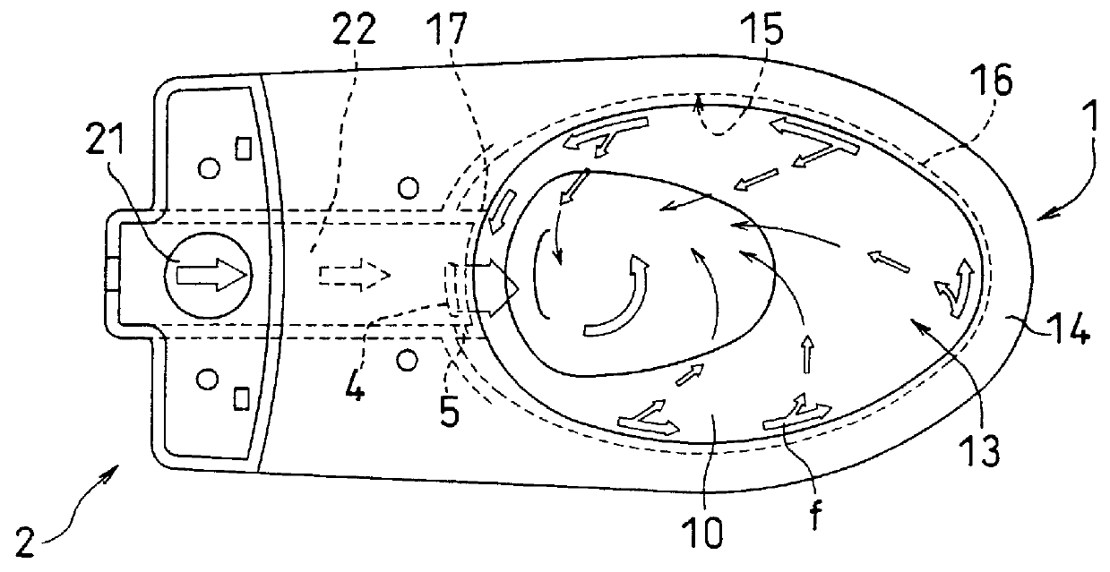
FIGS. 1 to 4 indicate a flush toilet A according to the first embodiment of the present invention. The flush toilet A is formed from porcelain with glaze coated thereon. As shown in FIGS. 1 and 2, the flush toilet A comprises a bowl section 1 at its front portion and a flush water supply and discharge section 2 at its rear portion.

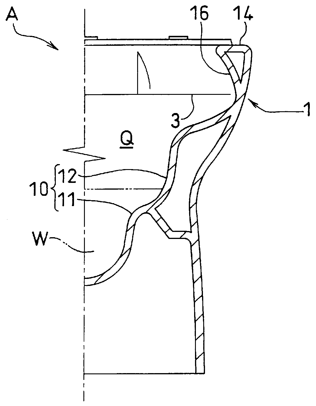
The bowl section 1 is configured in such a manner that flush water is stored at a lower portion of its inner space Q and that a waste receipt surface section is located at a front portion thereof and formed in such a bowl shape as receiving a waste product. The waste receipt surface section comprises a water chamber surface section 11 positioned so as to become under the water level of a water chamber W and a dry surface section 12 located above the water level of the water chamber W. The dry surface section 12 is formed in a shape such as a step-like shape which extends gradually and continuously toward the water chamber surface section ...

second embodiment

(Second Embodiment)

Next, a description will be made of the flush toilet A according to the second embodiment of the present invention with reference to FIGS. 9 to 11. The flush toilet A of the second embodiment is provided with the same reference numerals for the structuring elements identical to those of the flush toilet A of the first embodiment as described above.

Although the flush toilet A of the previous embodiment has the flush water passage 16 configured in an overhanging form over the entire periphery of the inner rim wall surface section 15 of the rim portion, the flush toilet A of this embodiment is configured such that a portion of the inner rim wall surface section 15 of the rim portion is shaped in an overhanging form. Therefore, the portion of the flush water passage 16 is shaped in an overhanging form, which is located in the position opposite to the flush water discharge section disposed on the interior side of the bowl section 1.

More specifically, the projection por...

third embodiment

(Third Embodiment)

A description will then be made of the flush toilet A according to the third embodiment with reference to FIGS. 17 to 20. The flush toilet of the third embodiment is configured such that the flush water passage 16 is shaped in an overhanging form inclining so as to hang over the entire periphery of the inner rim wall surface section 15 of the rim portion in substantially the same manner as the flush toilet of the first embodiment. On the other hand, the flush toilet of the third embodiment differs from the flush toilet of the first embodiment in that a forced flush water discharge outlet 40 is disposed in the position above the drain path inlet 18 disposed in the bottom portion of the bowl section 1 and above the water level close to the water level of the water chamber W in the bowl section 1. This configuration can promote a flow of the flush water into the drain path inlet 18 from the flush water passage 16. The structuring elements of the flush toilet of the th...


PUM


Abstract

PCT No. PCT/JP97/03706 Sec. 371 Date Apr. 14, 1999 Sec. 102(e) Date Apr. 14, 1999 PCT Filed Oct. 14, 1997 PCT Pub. No. WO98/16696 PCT Pub. Date Apr. 23, 1998The flush toilet has a waste receipt surface section (10) of a bowl section (1) formed continuously integrally with an inner rim wall surface section (15) of the rim portion disposed at a peripheral edge of an upper opening (13) of the bowl section (1) as a curved surface; and the inner rim wall surface section (15) of the rim portion acts as a flush water passage (16) of the bowl section. The flush water passage (16) of the bowl section is further configured such that the inner rim wall surface section (15) of the rim portion is shaped in an overhanging form inclining so as to hang over inside of the bowl section (1). The flush toilet of this configuration can be cleaned with ease and kept clean in sanitation.

Description

The present invention relates to a flush toilet of a washdown type, a siphon type, a siphon jet type, or the like.BACKGROUND TECHNOLOGYHitherto, as a main body of a flush toilet of a western type, there is generally known a flush toilet having the configuration such that a bowl section 100 is provided with a water supply and discharge system assembly 200 at its back portion, as shown in FIGS. 27(a) and 28(a).As shown in FIGS. 27(a) and 28(a), the bowl section 100 comprises a waste receipt surface section 110, a water chamber surface section 111 located underneath the water level of a water chamber section 120, and a dry surface section 112 formed continuously with the water chamber surface section 111 and located above the water level of the water chamber section 111.At the periphery of an upper opening of the bowl section 100 is provided a rim port-ion 130 having a predetermined width. The rim portion 130 comprises an inner peripheral wall 131, a rim rinse waterway 140, a water sup...

Claims


Application Information

Patent Timeline
Patent Type & Authority Patents(United States)
IPC IPC(8): E03D11/02E03D11/08E03D1/01E03D11/00
CPCE03D11/02E03D11/08E03D2201/40E03D2201/30E03D1/01E03D11/00
Inventor NAKAMURA, KENICHIYONEDA, TOSHIFUMI
Owner TOTO LTD
Why Eureka
Try Eureka