Load carrying lightweight pallet for spacecraft

a spacecraft and lightweight technology, applied in the direction of containers, cosmonautic components, cosmonautic parts, etc., can solve the problems of reducing the rigidity or stiffness of conventional pallets, and reducing the strength of conventional pallets. , to achieve the effect of reducing the cost of structural strength verification, facilitating the adaptation of pallets, and saving substantial structural strength verification costs

Inactive Publication Date: 2000-11-21
DAMELERKLESLER AVIATION
View PDF7 Cites 21 Cited by
  • Summary
  • Abstract
  • Description
  • Claims
  • Application Information

AI Technical Summary

Benefits of technology

The just described combination of features provides a pallet that can be constructed of modular elements in different sizes. These modular elements are modular elements that locate the strength of the pallet in those points of the pallet where a safe load acceptance is critical. Only a few modular components are required, whereby the components of a group are identical to one another. For example, all the longitudinal carrier beams are identical. Similarly, all the cross-connectors are identical. An important advantage of the present pallet is seen in that weak points or transitions between pallet components are avoided where force lines caused by loads are introduced into the pallet. Further, present pallet components are premanufactured with a minimum of milling operations, whereby a cost effective production is possible using flat sheet metal. The milling of the cross-connectors requires a removal of a small volume compared to the total volume of a prefabricated blank for making the cross-connectors. By simply selecting different thicknesses of the top and bottom sheet metal cover plates, it is easily possible to adapt the pallet to payloads having different masses or weights.
The present pallet can be produced, in spite of its optimized lightweight construction, of very simple components such as sheet metal, prefabricated sections or extrusion sections made of materials already certified for space travel purposes. As a result, further certifications, for example for pallets of different sizes, are no longer required. Moreover, proof that pallets of different strengths meeting the official strength requirements is easily provided even if cover plates of a different thickness are employed to accommodate a different payload. In that case it is merely necessary to enter the respective sheet metal characteristics such as the different thicknesses of the cover plates into a single finite elements model to quickly and economically provide the required proof. A costly new modelling of the pallet is not necessary when the payload is changed, whereby substantial structure strength verification costs can be saved.
The above-mentioned modular construction of preassembled elements further reduces the costs of the present pallets. For example, longitudinal carrier beams can be preassembled and two of such beams forming outer beams of the pallet are first interconnected at their ends to form a frame into which further beams are then inserted. Such a construction method makes it easy to adapt the lightweight pallet size individually to the requirements of any particular space flight mission.

Problems solved by technology

The just described conventional pallets have a relatively small rigidity or stiffness and a construction or layout that does not always provide the required strength at specific points where it is needed.
Conventional pallets are relatively heavy which reduces the payload.
Conventional pallets have a low resonance frequency which is undesirable for space flight missions where resonance vibrations must be avoided.
Yet another drawback is seen in the fact that the complicated pallet construction contributes to the manufacturing and assembly costs at least in certain instances.
For example, the machining of milled structures out of thick solid plates is expensive as well as time consuming, particularly where more than 95% of the material must be removed by milling.
Furthermore, a milling operation, especially where large volume portions are removed, can result in stress concentration locations within the pallet, whereby the possible payload is substantially reduced for such a pallet.
The connection of structural components by means of spacers and tension bolts is not only difficult and time consuming, it also provides a pallet, the structure of which is not ideally adapted to the load requirements to which such a pallet is exposed.
On the other hand, the riveting or screwing of shear take-up plates on both sides of a milled structure having a U-cross-sectional configuration is not advantageous in view of the denting characteristics of such shear plates.
Further, it is difficult to secure the shear plates to U-sectional stock, especially to the open side of such stock.
However, even this improved air freight pallet leaves room for improvement.

Method used


Image

  • Load carrying lightweight pallet for spacecraft
  • Load carrying lightweight pallet for spacecraft
  • Load carrying lightweight pallet for spacecraft

Examples


Embodiment Construction

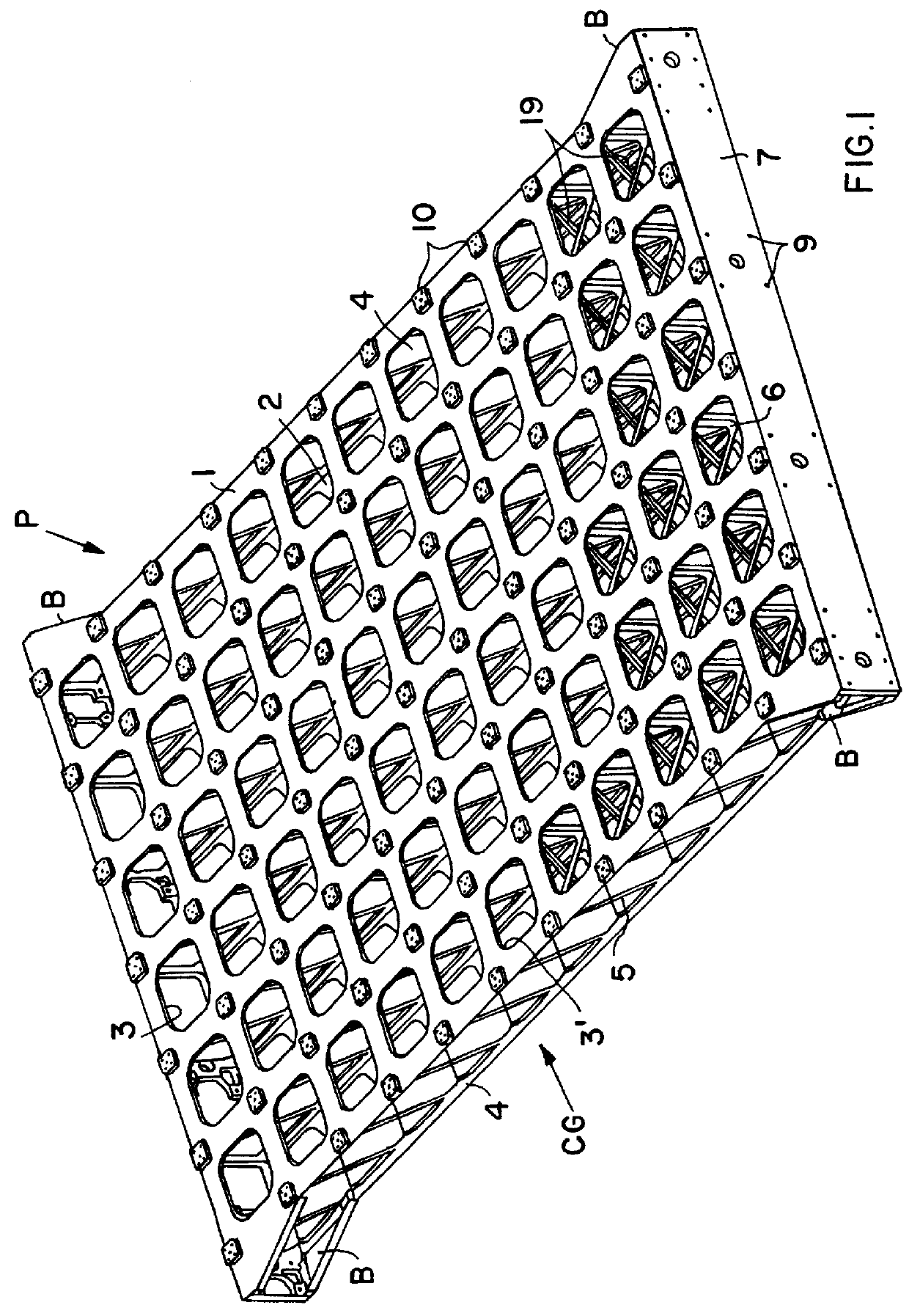
FIG. 1 shows a pallet P according to the invention with a flat sheet metal top cover plate 1 and a flat sheet metal bottom cover plate 2. A core grid CG is sandwiched between the cover plates 1 and 2. The top and bottom surfaces of the pallet P are particularly exposed to tension and pressure loads and these loads are primarily taken up by the cover plates 1 and 2 which are of identical construction. Each cover plate is provided with substantially rectangular cut-outs 3 for weight reduction. Each cut-out 3 has preferably a square or rectangular configuration with rounded corners 3' for an improved stress distribution.

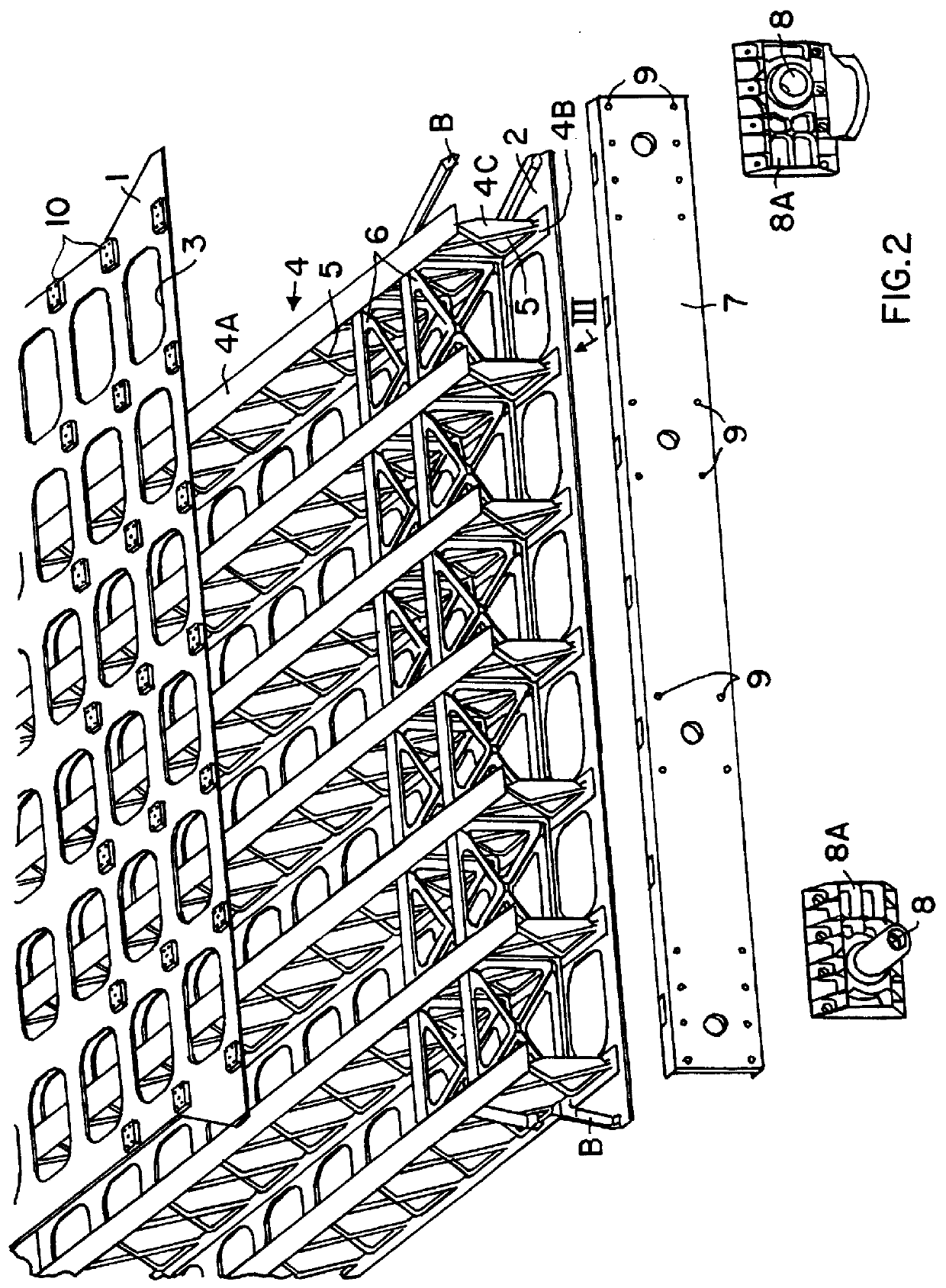
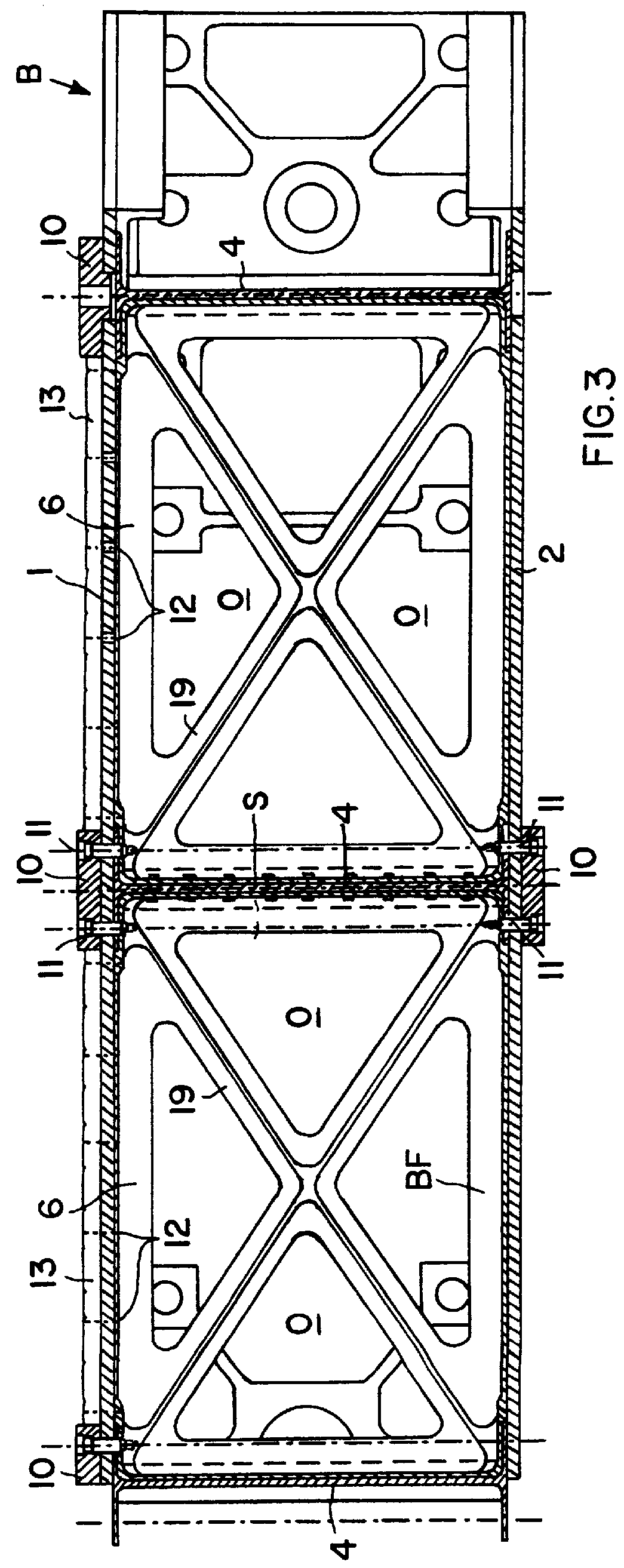
The core grid CG to which the cover plates 1 and 2 are secured, comprises longitudinal carrying beams 4 laterally interconnected by cross-connectors 6 best seen in FIG. 3. The connection of the cover plates 1 and 2 to the core grid CG can be accomplished in several ways, for example by screws, rivets, adhesive bonding, or welding. The longitudinal carrier beams 4 in the...


PUM


Abstract

A lightweight pallet especially for holding payloads in a spacecraft has a sandwich construction with a core grid of longitudinal carrier beams and cross-connectors mounted between a top flat sheet metal plate and a bottom flat sheet metal plate and a bottom sheet metal plate. A cross-beam is secured to the front end and to the rear end of the pallet. The cross-beams carry journal pins for mounting the pallets to respective yokes in the cargo bay of a spacecraft. The cover plates are provided with cut-outs forming square or rectangular holes with rounded corners. Hole patterns or threaded holes are provided for the connection of junction plates and payloads to the pallet. The junction plates are secured where the longitudinal beams and the cross-connectors meet. At least one of the two laterally outer longitudinal beams has a recess for the recessed mounting of payload supply unit such as a power supply. The recess is then closed again by a plate capable of taking up shear stress. The longitudinal beams and the cross-connectors are essentially hollow except for cross-ribs connecting the chords of the longitudinal beams and cross-trusses in a box frame of the cross-connectors.

Description

The invention relates to a lightweight pallet for holding heavy loads particularly in spacecraft. Such pallets have a sandwich structure with an upper cover plate and a lower cover plate made of sheet metal and connected to each other by a grid structure.BACKGROUND INFORMATIONConventional pallets are used in spacecraft for transporting payloads into outer space, for example to a space station or for transporting payloads back to earth from a spacecraft or station. For this purpose the payloads are either rigidly or releasibly secured to the pallets. The pallets in turn are mounted in the spacecraft generally in a so-called space shuttle. The mounting of the pallet in the cargo bay of the shuttle is usually accomplished by a yoke or bail and a number of journal bearing pins for securing the pallet to the bail.One type of conventional pallet particularly constructed for the above purpose has an upper milled structure and a lower milled structure. These two milled structures are connec...

Claims


Application Information

Patent Timeline
Patent Type & Authority Patents(United States)
IPC IPC(8): B64G1/22B65D19/00B65D19/44B65D19/38
CPCB64G1/22B65D19/44B65D19/0002B65D2519/00572B65D2519/00024B65D2519/00059B65D2519/00129B65D2519/00273B65D2519/00278B65D2519/00288B65D2519/00308B65D2519/00318B65D2519/00363B65D2519/00378B65D2519/00447B65D2519/00557B65D2519/00562
Inventor JACKEL, ROLANDGOLBECK, ORTWIN
Owner DAMELERKLESLER AVIATION
Why Eureka
Try Eureka