Apparatus and method for fixing electrodes in a blood vessel

Inactive Publication Date: 2000-12-12
MEDTRONIC INC
View PDF31 Cites 458 Cited by
  • Summary
  • Abstract
  • Description
  • Claims
  • Application Information

AI Technical Summary

Benefits of technology

The lead body is preferably highly miniaturized in diameter to avoid obstructing blood flow through the aligned retention stent lumen and distal electrode support lumen and so flexible that it does not have appreciable column strength. The arrangement of the present invention advantageously provides a simpli

Problems solved by technology

Over the years of implantation, the lead conductors and insulation are subjected to cumulative mechanical stresses, as well as material reactions as described below, that can result in degradation of the insulation or fractures of the lead conductors with untoward effects on device performance and patient well being.
Such relatively large and stiff lead bodies were disadvantageous in a number of respects.
The large diameter body made it difficult to implant more than one lead through the venous system.
The column strength of such relatively large and stiff lead bodies often was insufficient to maintain the pace/sense electrodes in the atrial appendage or ventricular apex, and physicians often resorted to leaving the stylets in place, resulting in fracture of the lead bodies.
Once the lead bodies fibrosed in, they were difficult to retract from the heart if they needed to be replaced.
The increased number of separate polarity coiled wire conductors is difficult to accommodate in the conventional coaxial coiled wire conductor winding arrangement employing

Method used


Image

  • Apparatus and method for fixing electrodes in a blood vessel
  • Apparatus and method for fixing electrodes in a blood vessel
  • Apparatus and method for fixing electrodes in a blood vessel

Examples


Embodiment Construction

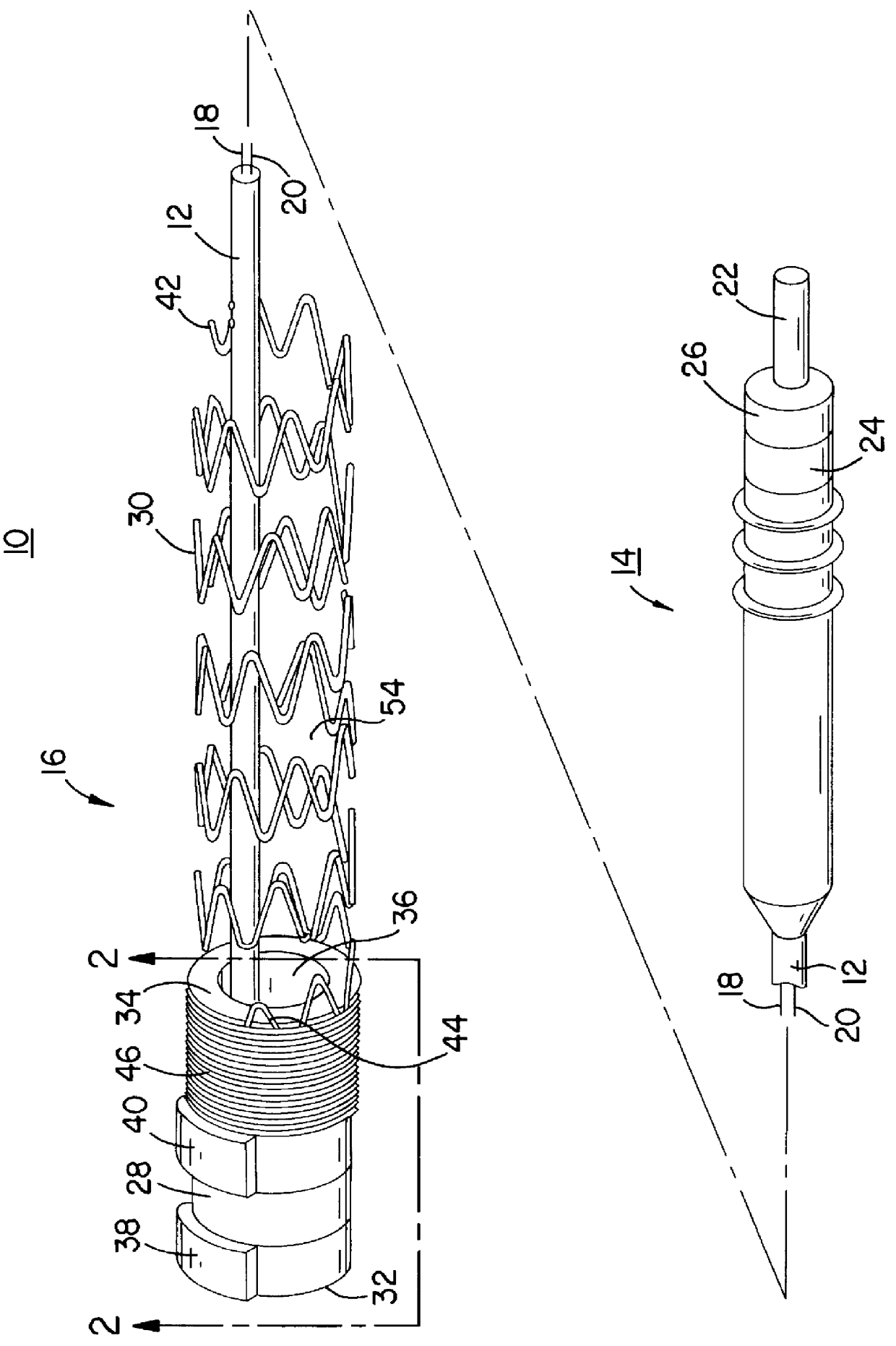
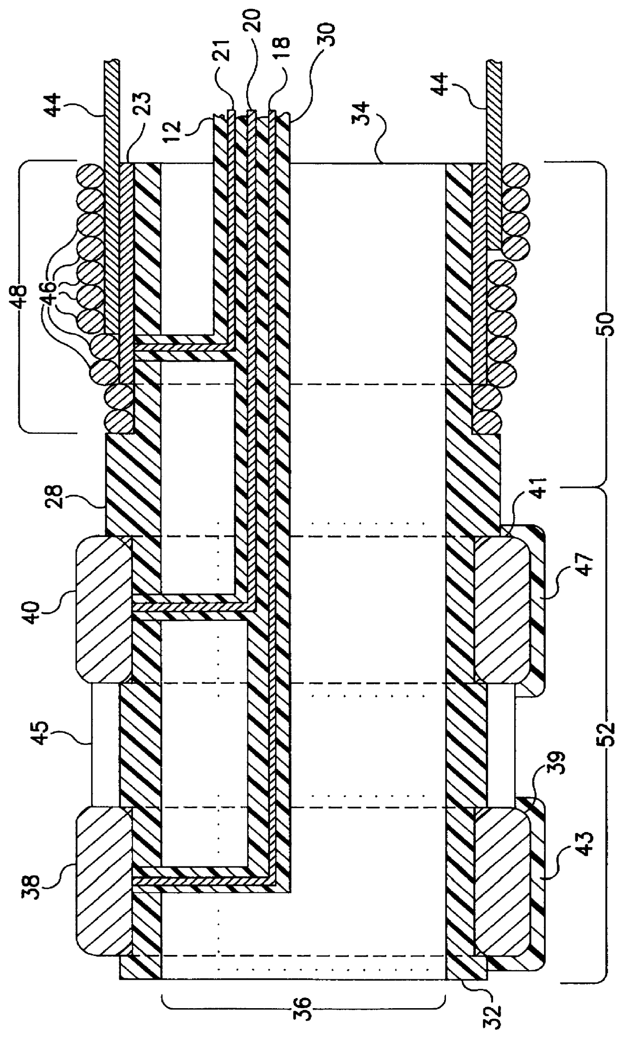
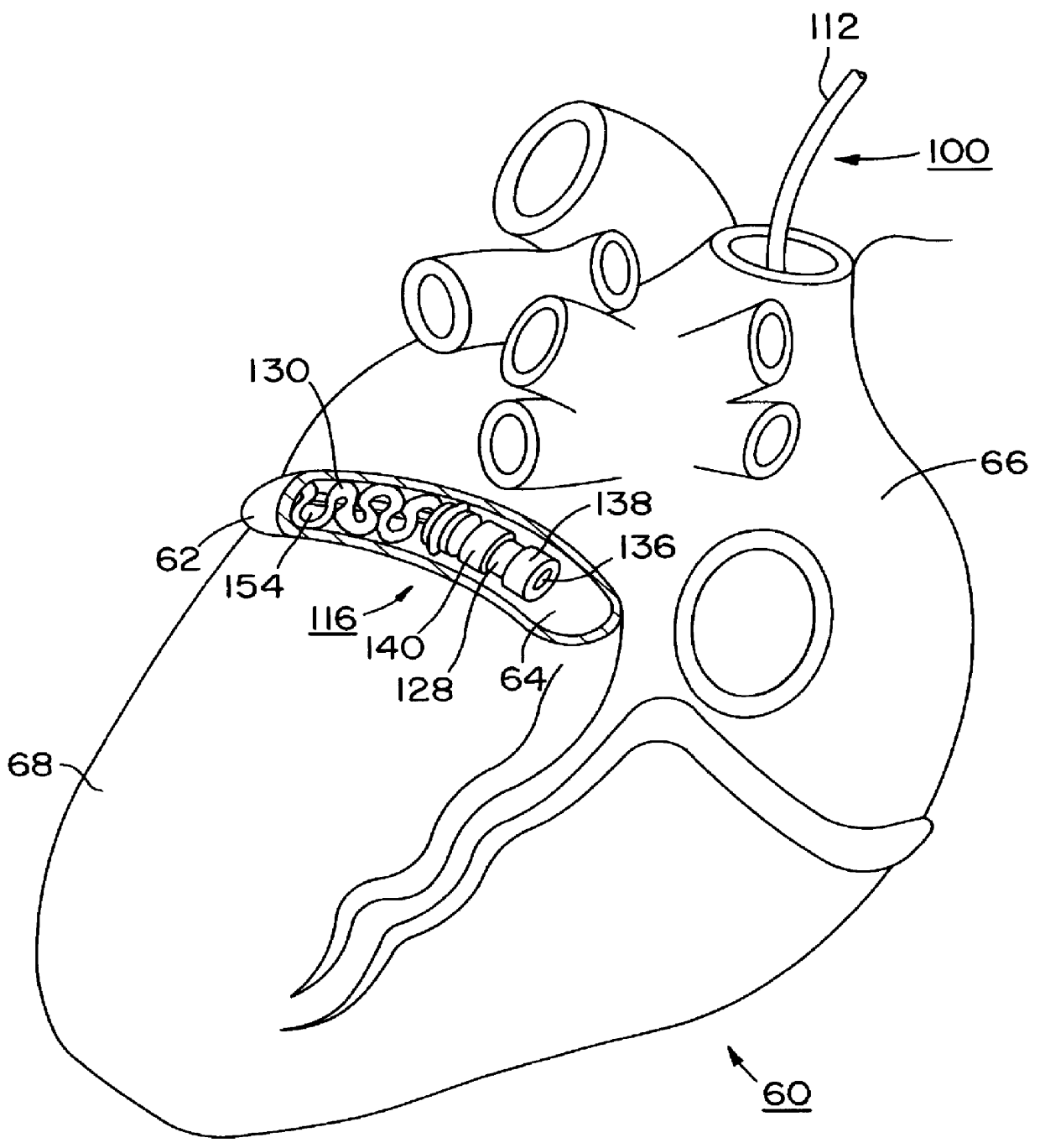
In the following detailed description, references are made to illustrative embodiments endocardial leads adapted to be located in cardiac blood vessels for carrying out the invention. It is understood that the invention may be practiced in respect to other body implantable leads located in elongated body lumens of body organs, ducts or tracts where body fluid flows.

The invention and its preferred embodiment may be implemented in unipolar, bipolar or multi-polar, endocardial, cardiac pacing and / or sensing leads having one or more pace / sense electrode(s) or sense electrode(s), respectively, at or adjacent the distal lead end. Similarly, the invention and its preferred embodiments may be implemented in endocardial cardiac defibrillation / cardioversion leads including at least one cardioversion / defibrillation electrode and optionally including one or more pace / sense electrode(s) at or adjacent the distal lead end. Moreover, other sensors for sensing a physiologic parameter may be incorpo...


PUM


Abstract

Endocardial implantable cardiac leads are disclosed for applying electrical stimulation to and/or sensing electrical activity of the heart at one or more distal electrode positioned at a cardiac implantation site within a cardiac vessel adjacent to and at a desired orientation to the left ventricle or atrium of the heart. The distal electrode(s) is supported by a tubular electrode support having a diameter large enough to bear against the blood vessel wall and a support lumen that allows blood to flow through it. A retention stent extends proximally from a distal stent end fixed to the tubular electrode support to a proximal stent end. After advancement to the cardiac implantation site employing a lead delivery mechanism, the retention stent is expandable from a collapsed stent state in which the outer diameter of the retention stent is less than the inner diameter of the vessel to an expanded stent state. The expanded stent is lodged against the blood vessel wall and inhibits movement of the stent and distal electrode support. The expanded stent lumen is aligned with the electrode support lumen for allowing blood to flow through the aligned electrode support lumen and expanded stent lumen. The retention stent may take any of the known forms that can be introduced in the collapsed stent state within an introducer lumen or mounted to an introducer and can either self-expand upon release in the blood vessel or be mechanically expanded within the blood vessel.

Description

The present invention relates to endocardial implantable cardiac leads for applying electrical stimulation to and / or sensing electrical activity of the heart at one or more electrode positioned at a cardiac implantation site within a cardiac blood vessel adjacent a heart chamber and more particularly to such a lead particularly adapted to be implanted in the coronary sinus to maintain pace / sense electrodes at a desired orientation to the left ventricle or atrium of the heart.Implantable medical electrical stimulation and / or sensing leads are well known in the fields of cardiac stimulation and monitoring, including cardiac pacing and cardioversion / defibrillation, and in other fields of electrical stimulation or monitoring of electrical signals or other physiologic parameters of the body. A pacemaker or cardioverter / defibrillator implantable pulse generator (IPG) or a cardiac monitor is typically coupled to the heart through one or more of such endocardial leads. The proximal end of s...

Claims


Application Information

Patent Timeline
IPC IPC(8): A61B5/042A61B5/0408A61N1/05
CPCA61B5/042A61N1/056A61B5/6853A61N2001/0585A61B5/283A61B5/29
Inventor SPREIGL, WILLIAM T.HESS, DOUGLAS NHEYNEN, HENRI G.STRUBLE, CHESTER I.VON VENROOIJ, PAULUS C.
Owner MEDTRONIC INC
Why Eureka
Try Eureka