High frequency measuring circuit

a high frequency measurement and circuit technology, applied in the direction of instruments, specific gravity measurement, mechanical means, etc., can solve the problems of increasing the mass of the acoustic wave device, changing the frequency at which the piezoelectric acoustic wave device will resonate, and correspondingly small changes in the operating frequency of the piezoelectric oscillator

Inactive Publication Date: 2000-12-19
FISHER CONTROLS INT LLC
View PDF40 Cites 38 Cited by
  • Summary
  • Abstract
  • Description
  • Claims
  • Application Information

AI Technical Summary

Problems solved by technology

This deposit increases the mass of the acoustic wave device and thereby changes the frequency at which the piezoelectric acoustic wave device will resonate.
However, when low concentrations are being measured, the change in operating frequency of the piezoelectric oscillator is correspondingly small.
The difficulty of measuring these small variations in frequency is increased because of the relatively high frequency at which the piezoelectric oscillator operates, caused by the high resona...

Method used


Image

  • High frequency measuring circuit
  • High frequency measuring circuit
  • High frequency measuring circuit

Examples


Embodiment Construction

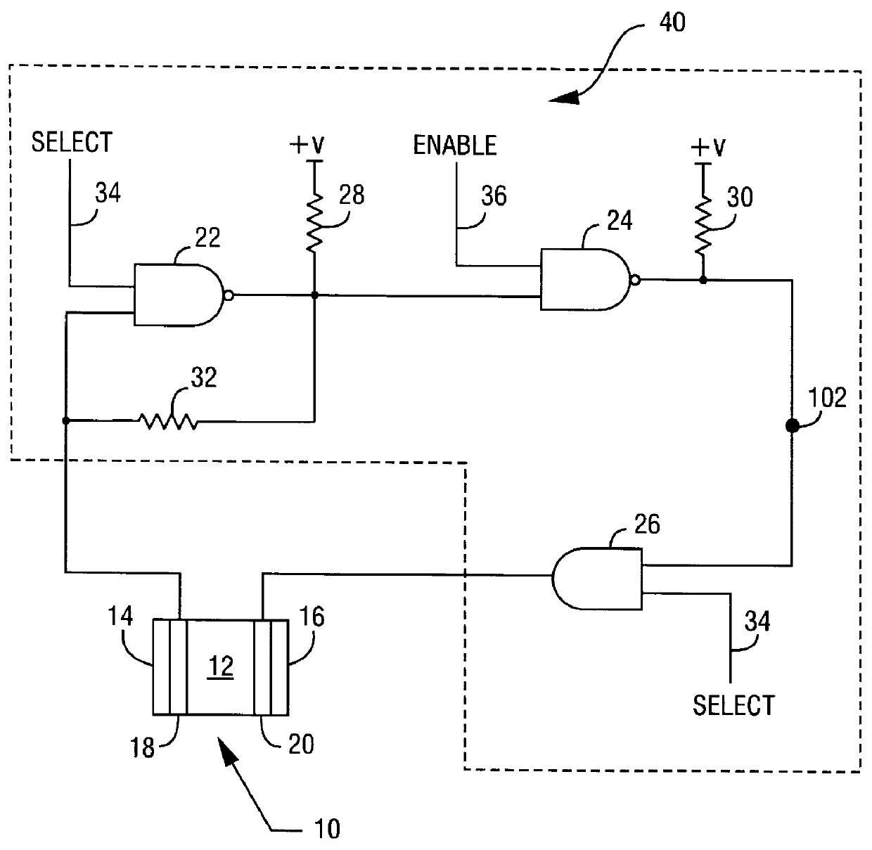
Turning now to the drawings and referring initially to FIG. 1, a quartz crystal microbalance (QCM) circuit is shown comprising a QCM gas sensor 10 and oscillator circuit 40. The QCM gas sensor 10 comprises a quartz crystal substrate 12, polymer coatings 14 and 16, and electrodes 18 and 20 located between the substrate and the coatings. The oscillator circuit 40 comprises NAND gates 22 and 24, and AND gate 26, connected in series. Resistor 28 is connected between the output of NAND gate 22 and circuit power supply voltage +V, and resistor 30 is connected between the output of NAND gate 24 and circuit power supply voltage +V. Resistor 32 is connected across NAND gate 22, connecting a first input to the output. A select signal 34 is connected to the second input of NAND gate 22, and the same select signal is also connected to an input of AND gate 26. An enable signal 36 is connected to an input of NAND gate 24.

When the select signal 34 and enable signal 36 are both high, NAND gate 22 a...


PUM


Abstract

An electrical circuit and method for measuring small variations in a high frequency signal is disclosed. The circuit generates a coarse measurement of the input signal frequency and a reference signal having the same frequency as the frequency represented by the coarse measurement. The circuit measures the difference in frequency between the input signal and the reference signal, and adds the coarse measurement and the difference measurement to determine the frequency of the input signal. The circuit may be used in conjunction with a piezoelectric acoustic wave device and oscillator to provide an apparatus for accurately measuring low concentrations of a gas.

Description

A. Field of the InventionThe present invention relates generally to a circuit for measuring frequency variations in a high frequency signal and, more particularly, to a circuit for measuring the response from a quartz crystal microbalance gas sensor.B. Description of the Related ArtPiezoelectric acoustic wave devices, including quartz crystal microbalance (QCM) devices, have been used to measure the concentration of moisture and particulates in gas streams, the accumulation of solids in fluid compositions, and similar applications for measuring the concentration of a substance. These acoustic wave devices typically are coated with a material that has an affinity with the substance whose concentration is being measured. The acoustic wave device operates by measuring the amount of the substance deposited onto the surface of the device. This deposit increases the mass of the acoustic wave device and thereby changes the frequency at which the piezoelectric acoustic wave device will reso...

Claims


Application Information

Patent Timeline
IPC IPC(8): G01R23/00G01R23/10
CPCG01R23/10
Inventor DILGER, JOHN P.DIELSCHNEIDER, NILE K.
Owner FISHER CONTROLS INT LLC
Why Eureka
Try Eureka