Aftercooler having bypass passage integrally formed therewith

a bypass passage and aftercooler technology, applied in the direction of positive displacement liquid engines, fluid pressure control, instruments, etc., can solve the problems of aftercooler devices "freezing up", washing away lubricants, and possibly freezing at critical points of the system, and achieve the effect of rapid thawing

Inactive Publication Date: 2001-01-02
WESTINGHOUSE AIR BRAKE CO
View PDF9 Cites 30 Cited by
  • Summary
  • Abstract
  • Description
  • Claims
  • Application Information

AI Technical Summary

Benefits of technology

One object of the present invention is the provision of an aftercooler having a radiator unit and being equipped with a bypass line and a bypass flow proportioning mechanism for proportioning flow of compressed fluid between the radiator unit and the bypass channel to thereby rapidly thaw any frozen condensate that may form in the radiator unit of the aftercooler.

Problems solved by technology

However, perhaps due to insufficient circulation of the ambient air to such location, this known arrangement frequently fails to sufficiently cool the compressed air and thereby provide adequate removal of suspended water vapor.
However, if used in freezing or near freezing ambient temperatures, such an aftercooler device may "freeze up".
That is, the condensed water which forms within the aftercooler can freeze within the relatively narrow passages thereof, substantially blocking or at least considerably restricting the air flow therethrough.
The disadvantages of allowing uncooled compressed air to flow directly into the pneumatic system have been pointed out above: e.g., the high temperature compressed air carries excess water vapor that condenses as it cools to ambient temperature in its passage through the various pneumatic components, washing away lubricants and possibly freezing at critical points of the system.
The known system, by removing the aftercooler for significant periods of time clearly raises the possibility of such problems.

Method used


Image

  • Aftercooler having bypass passage integrally formed therewith
  • Aftercooler having bypass passage integrally formed therewith

Examples


Embodiment Construction

, particularly when such description is taken in conjunction with the attached drawing Figures and with the appended claims.

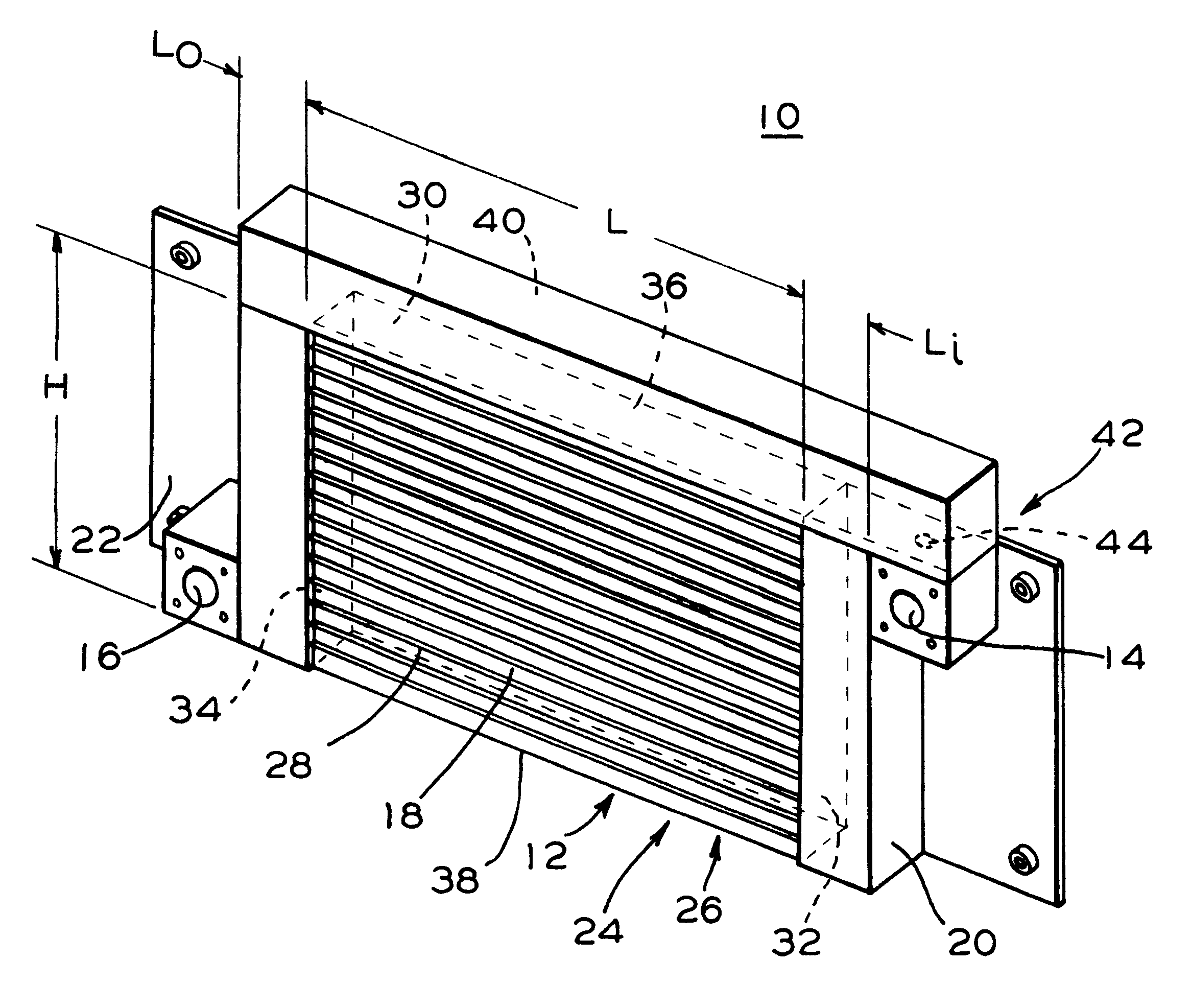
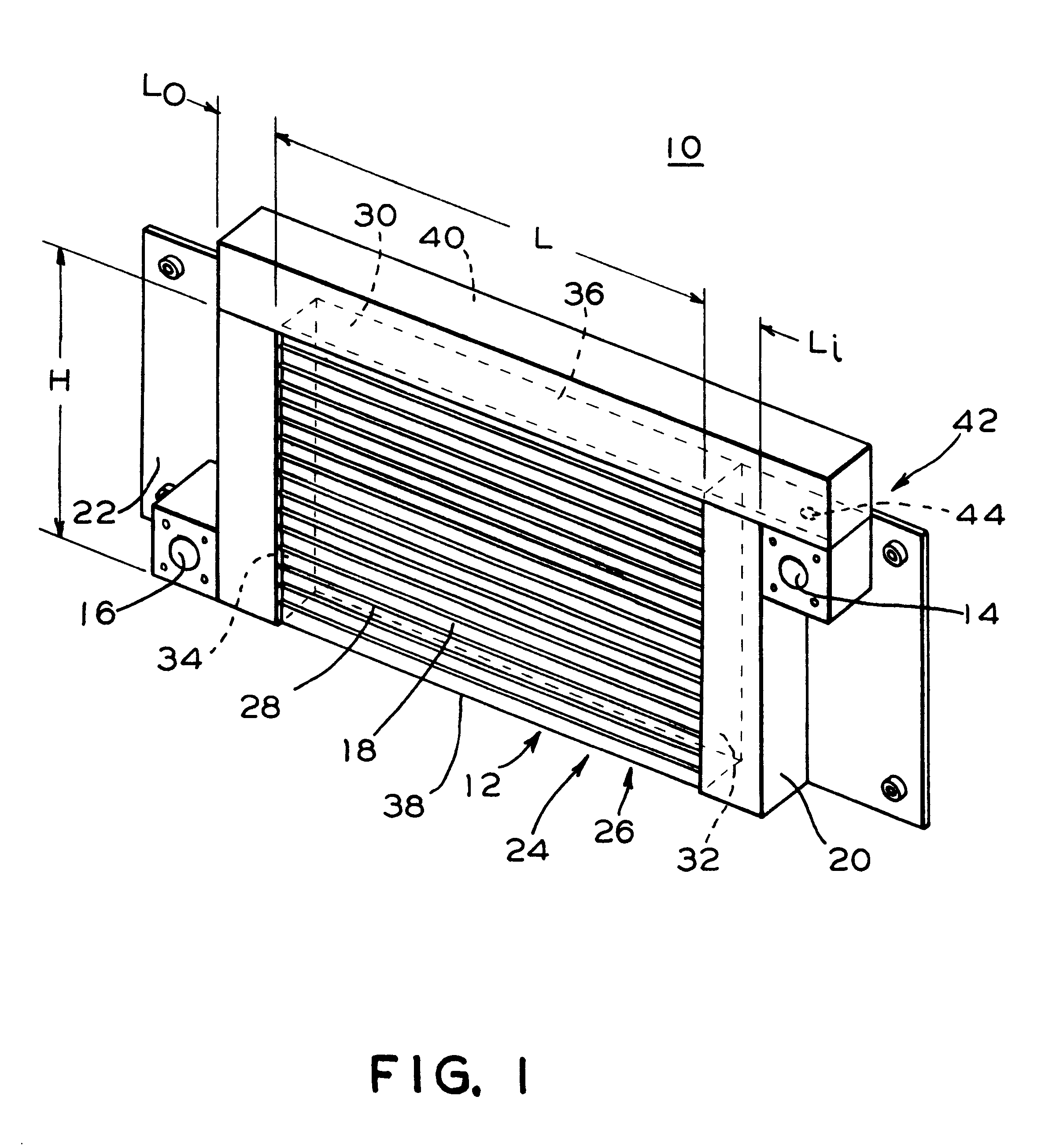
In one aspect, the invention generally features an aftercooler for cooling a compressed fluid exiting from a compressor, the aftercooler including a radiator unit for receiving the compressed fluid exiting from the compressor and for cooling the compressed fluid, the radiator unit having an inlet for receiving the compressed fluid, an outlet for discharging the compressed fluid and a plurality of heat exchange passageways connecting the inlet and the outlet for transferring heat from the compressed fluid. The aftercooler also includes a bypass channel for bypassing the plurality of heat exchange passageways, the bypass channel extending from a first point substantially adjacent the inlet of the radiator unit to a second point substantially adjacent the outlet of the radiator unit. The aftercooler further includes a flow proportioning mechanism. The flow proport...


PUM


Abstract

An aftercooler for cooling a compressed fluid exiting from a compressor, the aftercooler including a radiator unit for receiving the compressed fluid exiting from the compressor and for cooling the compressed fluid, the radiator unit having an inlet for receiving the compressed fluid, an outlet for discharging the compressed fluid and a plurality of heat exchange passageways connecting the inlet and the outlet for transferring heat from the compressed fluid. The aftercooler also includes a bypass channel for bypassing the plurality of heat exchange passageways which extends from a first point substantially adjacent the inlet of the radiator unit to a second point substantially adjacent the outlet of the radiator unit. The aftercooler also includes a bypass flow proportioning mechanism that is effective to proportion the flow of the compressed fluid exiting from the compressor and flowing through the aftercooler between the radiator unit and the bypass channel dependent upon a pressure differential across the radiator unit. Preferably, the bypass flow proportioning mechanism is a substantial restriction disposed along the bypass channel which operates to continuously proportion flow between the radiator unit and the bypass channel. The bypass channel is formed substantially integrally with the radiator unit. Preferably, the plurality of heat exchange passageways are arranged to form an array and at least a portion of a length of the bypass channel extends contiguous with a portion of a periphery of the array of the heat exchange passageways.

Description

The present invention relates, in general, to compressors and, more particularly, the present invention relates to an aftercooler for a compressor used in a pneumatic braking system, the aftercooler being effective to condense water vapor contained within the compressed gas by a cooling effect. The condensed vapor may thereafter be readily removed from the compressed fluid or gas (e.g., air).Such aftercoolers find particular application in pneumatic braking systems, particularly such pneumatic braking systems as are employed in the rail transportation industry (e.g., trains and light rail vehicles), but other applications are also possible.Pneumatic braking systems are widely employed in rail transport and, additionally, in road based transport, such as heavy trucks. Such pneumatic braking systems utilize air at an elevated pressure which is commonly provided by an onboard compressor that supplies the air compressed thereby to at least one compressed air reservoir. The compressed ai...

Claims


Application Information

Patent Timeline
Patent Type & Authority Patents(United States)
IPC IPC(8): F04B39/06F28F27/00F28F27/02F28B9/00F28D1/04F28D1/053
CPCF04B39/06F28B9/005F28D1/05366F28F27/02F28F2250/06
Inventor BOSTEDO, ROBERTCUNKELMAN, BRIAN L.
Owner WESTINGHOUSE AIR BRAKE CO
Why Eureka
Try Eureka