Encoding method and apparatus, decoding method and apparatus and recording medium

a multi-channel acoustic signal and encoding technology, applied in the field of encoding methods and encoding apparatuses for multi-channel acoustic signals, can solve the problems of obstructing the reduction in achieving non-optimum results, and reducing the size of reproducing means

Inactive Publication Date: 2001-01-02
SONY CORP
View PDF50 Cites 80 Cited by
  • Summary
  • Abstract
  • Description
  • Claims
  • Application Information

AI Technical Summary

Problems solved by technology

However, if the transform block length for transform is lengthened, more work area is required for transform, thus obstructing reduction in size of reproducing means.
However, the actual noise feeling is not psychoacoustically optimum because the psychoacoustic masking effect is not exploited.
However, if this technique is used to measure characteristics of a sine wave input, non-optimum results are obtained because of the fixed allocation of bits among the critical bands.
Since the relation between the normalization coefficient information and the quantization fineness information is set at the time of setting the standard, it becomes impossible to introduce the quantization fineness control based on a more advanced psychoacoustic model in future.
This sets a limit to improving the compression efficiency by encoding.

Method used


Image

  • Encoding method and apparatus, decoding method and apparatus and recording medium
  • Encoding method and apparatus, decoding method and apparatus and recording medium
  • Encoding method and apparatus, decoding method and apparatus and recording medium

Examples


Embodiment Construction

Referring to the drawings, preferred embodiments of the present invention will be explained in detail.

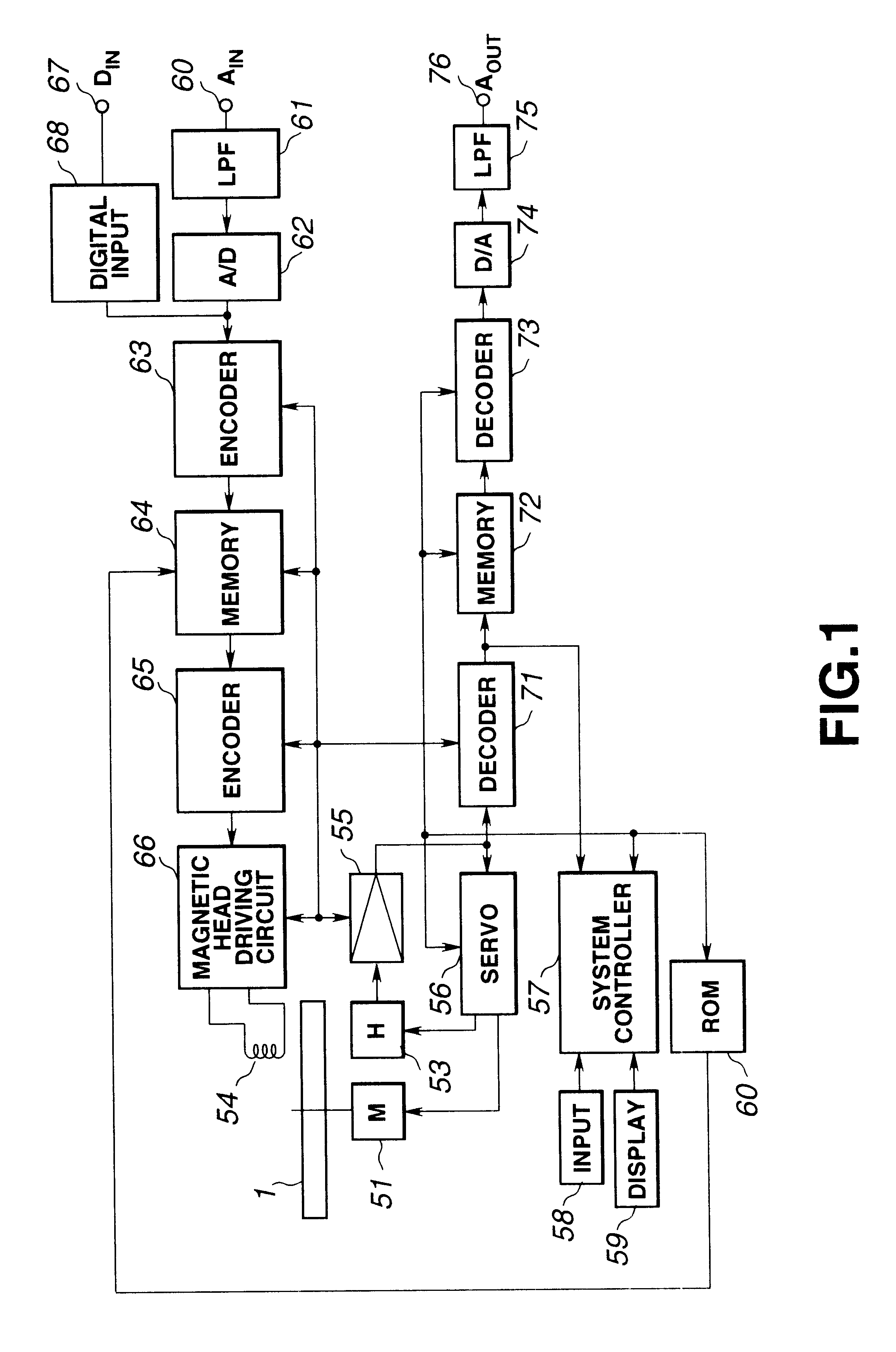
FIG. 1 shows the schematic structure of a compressed data recording / reproducing apparatus according to an embodiment of the present invention.

In the compressed data recording / reproducing apparatus shown in FIG. 1, a magneto-optical disc 1 run in rotation by a spindle motor (M) 51 is used as a recording medium. During data recording on the magneto-optical disc 1, a modulating magnetic field corresponding to recording data is applied by a magnetic head (H) 54, as the laser light beam is illuminated by, for example, a magnetic head 53, by way of performing; so-called magnetic field modulation recording for recordings data along a recording track of the magneto-optical disc 1. During reproduction, the recording track of the magneto-optical disc 1 is traced by the laser light by an optical head 53 for photomagnetic data reproduction.

The optical head 53 is made up of a laser light source,...


PUM

PropertyMeasurementUnit
time-domainaaaaaaaaaa
frequencyaaaaaaaaaa
band-widthaaaaaaaaaa

Abstract

An encoding method and apparatus and a decodings method and apparatus in which the encoded information is decreased in volume and in which the encoding and decoding operations are performed with a smaller processing volume and a smaller buffer memory capacity. The apparatus includes a low range signal splitting circuit for separating low-range side signal components from L and R channel signals converted by a transform circuit into spectral signal components, and a channel synthesis circuit for synthesizing (L+R) channel signal components from the L and R channel spectral signal components. The apparatus also includes a high range signal separating circuit for separating the high range side signal components from the (L+R) channel signal components, a signal component encoding circuit for compression-encoding low-range side signal components and a signal component encoding circuit for compression-encoding the normalization coefficient information obtained on normalization of the (L+R) channel high-range signal components.

Description

1. Field of the InventionThis invention relates to an encoding method and apparatus for encoding multi-channel acoustic signals, a decoding method and apparatus for decoding the encoded information and a recording medium having the encoded signals recorded thereon.2. Description of Related ArtThere has so far been proposed a recording medium capable of recording signals such as the encoded acoustic information or the music information (referred to hereinafter as audio signals), such as a magneto-optical disc. Among methods for high-efficiency encoding of the audio signals, there are a so-called transform coding which is a blocking frequency spectrum splitting method of transforming a time-domain signal into frequency domain signals by orthogonal transform and encoding the spectral components from one frequency band to another, and a sub-band encoding (SBC) method, which is a non-blocking frequency spectrum splitting method of splitting the time-domain audio signals into plural frequ...

Claims


Application Information

Patent Timeline
Patent Type & Authority Patents(United States)
IPC IPC(8): G11B20/00G11B20/10H04H5/00H04B1/66G10L19/00G06F17/14H04H20/88
CPCG11B20/00007G11B20/10527H04B1/665H04H20/88H04N19/132
Inventor TSUTSUI, KYOYASHIMOYOSHI, OSAMU
Owner SONY CORP
Why Eureka
Try Eureka