Systems and methods for hydrocarbon recovery

Inactive Publication Date: 2001-01-16
ELIAS RAMON +2
View PDF34 Cites 331 Cited by
  • Summary
  • Abstract
  • Description
  • Claims
  • Application Information

AI Technical Summary

Benefits of technology

An oil recovery operation of this type according to the present invention that utilizes wells equipped in the usual manner may be cumbersome to access and difficult to maintain because of the relative closeness of the wells. One aspect of this invention involves the use of a recessed wellhead to reduce this effect of congestion. A recessed or below-grade wellhead system; a container for a below-grade wellhead; and a wellhead with appropriate covering which can support significant weight, such as the weight of a large truck or other vehicle in a field or area with a plurality of such wellheads alleviates the congestion associated with certain conventional systems and designs. Furthermore, the environment is rendered more pleasing due to the use of recessed installations since conventional surface installations may be perceived as an unsightly gathering of mechanical equipment and thus damaging to the environment. The present invention teaches a variety of reinforced cellars or containers useful with such below-grade wellheads such as prefabricated cement culverts and/or sewage pipes and any other similar low cost container, duct, cellar, and/or construction items.
According to certain embodiments of the present invention lower cost well designs are used that are adapted to lower pressures, lower temperatures, lower injection rates, lower production rates and sometimes shorter life th

Problems solved by technology

Higher steam injection rates cannot be used for effectively and safely producing hydrocarbons from diatomite unless, according to the present inve

Method used


Image

  • Systems and methods for hydrocarbon recovery
  • Systems and methods for hydrocarbon recovery
  • Systems and methods for hydrocarbon recovery

Examples


Embodiment Construction

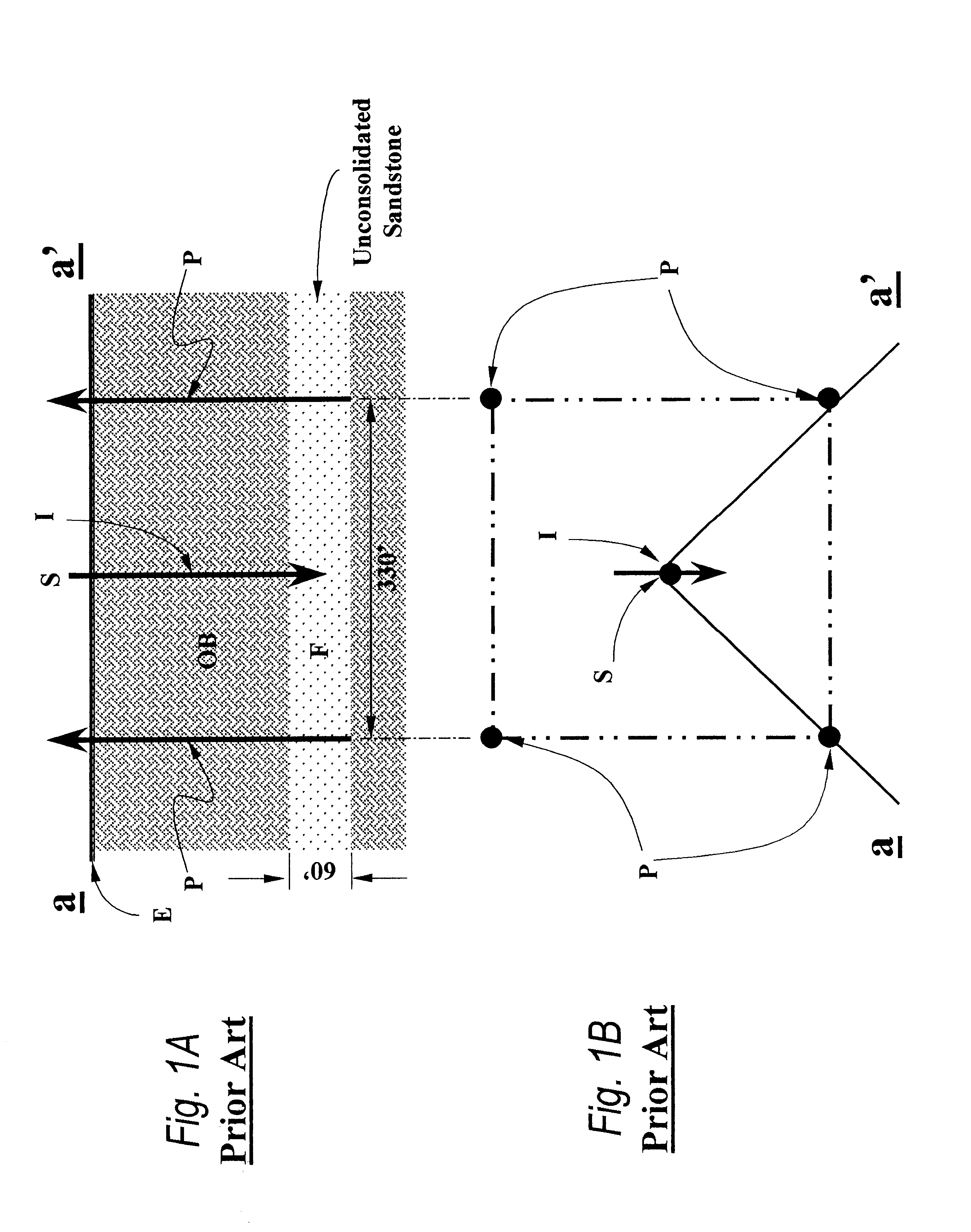
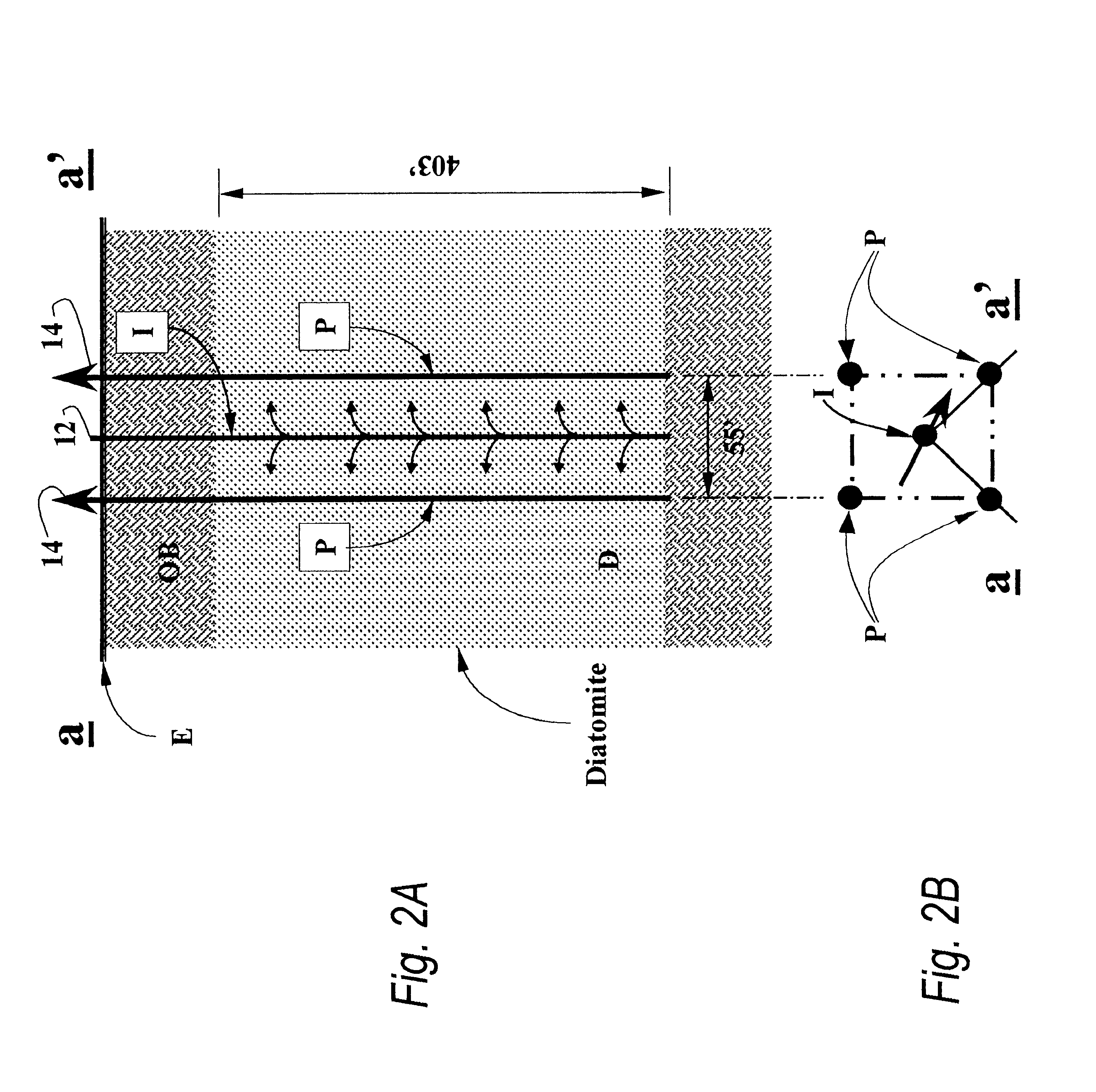
(including the calculations for prior art well spacing and for spacing according to the present invention) is based on a known equation adapted from work by Muskat about 50 years ago. Although it serves quite well to illustrate the interaction between spacing, formation thickness, fluid mobility, and oil concentration, on the injection rate and the life of a project, today such calculations are usually done with numerical simulators, which can include the additional effects of multiple compressible fluids under the effects of gravity and capillary forces, variable pressure differences, damaged zones near wells, selective injection and production intervals, and heterogeneities within the formation. Detailed calculations using more sophisticated numerical simulation methods run by computer yield similar results. But the substance of the numerical results are those already shown in Example II.

Another factor, whose significance was recognized by the present invention, favoring the use o...


PUM


Abstract

A method has been invented for recovering hydrocarbons from an earth formation containing hydrocarbons, the method including injecting a recovery injectant into the earth formation at a plurality of injection points spaced apart by about 14 to about 208 feet, and producing hydrocarbons from the formation with at least one producer well. In one aspect the method includes injecting steam into an earth formation which contains oil bearing diatomite at a plurality of injection points spaced apart by about 14 to about 208 feet, and producing hydrocarbons from the formation with a one or more producer wells extending into the oil bearing diatomite formation, with a plurality of producer wells spaced apart by a distance ranging between about 14 to about 149 feet, injecting steam into the oil bearing diatomite at an injection rate of between about 10 to about 149 barrels of steam per day per hundred feet thickness of diatomite, and injecting the steam at a pressure between about 10 p.s.i. to about 260 p.s.i. The present invention also discloses a method for treating a hydrocarbon-bearing diatomite formation including applying an artificial overburden over at least a portion of the formation and applying a variable well spacing as needed. A field on an earth formation has been invented for recovering hydrocarbons, the earth formation having an earth surface above it, the field including a plurality of injector well and a plurality of producing wells, the field including at least one injector well per acre of earth surface above the earth formation and at least one producing well per acre. Certain parts of the wells may be in below-grade chambers.

Description

This invention is directed to systems and methods for recovering hydrocarbons from the earth, and in one particular aspect to such recovery from diatomaceous and other hydrocarbon-bearing rock occurring at shallow depths and sometimes outcropping at the surface; to such systems and methods using recovery techniques involving the injection of substances and / or materials that improve the hydrocarbon recovery performance such as but not limited to steam injection; and, in one particular aspect, to such systems and methods including an artificial shield on a formation for reducing or eliminating the escape of injected materials and / or substances and / or pollutants to the surface and / or environment. In one aspect, the present invention is directed to a recessed wellhead system.DESCRIPTION OF RELATED ARTThe prior art discloses knowledge of a variety of known liquid and solid hydrocarbon deposits that have not been exploited because of unfavorable economics or unavailable and / or inadequate ...

Claims


Application Information

Patent Timeline
IPC IPC(8): E21B43/16E21B43/24
CPCE21B43/24
Inventor ELIAS, RAMONPRATS, MICHAEL
Owner ELIAS RAMON
Why Eureka
Try Eureka