Liquid ejection head with a heat generating surface that is substantially flush and/or smoothly continuous with a surface upstream thereto

a heat generating surface and liquid ejection technology, which is applied in printing and other directions, can solve the problems of deteriorating energy use efficiency and ejection force, large amount of deposition, and unstable ink ejection

Inactive Publication Date: 2001-01-16
CANON KK
View PDF36 Cites 324 Cited by
  • Summary
  • Abstract
  • Description
  • Claims
  • Application Information

AI Technical Summary

Problems solved by technology

However, the amount of the deposition may be large depending on the materials of the ink.
If this occurs, the ink ejection becomes unstable.
In addition, the deformation of the flexible film is not so...

Method used


Image

  • Liquid ejection head with a heat generating surface that is substantially flush and/or smoothly continuous with a surface upstream thereto
  • Liquid ejection head with a heat generating surface that is substantially flush and/or smoothly continuous with a surface upstream thereto
  • Liquid ejection head with a heat generating surface that is substantially flush and/or smoothly continuous with a surface upstream thereto

Examples


example 2

(Head Example 2)

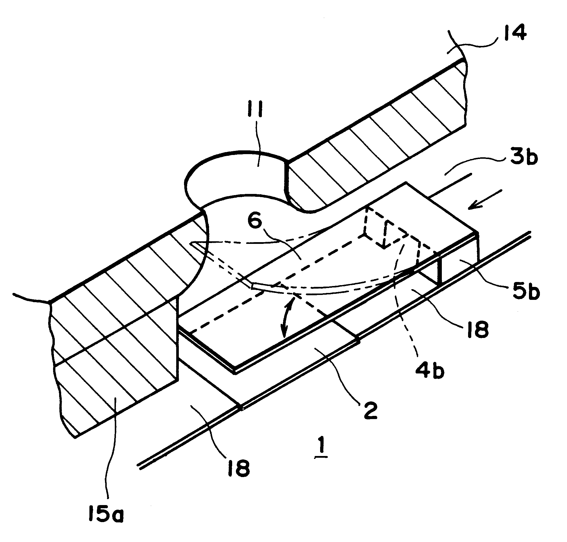
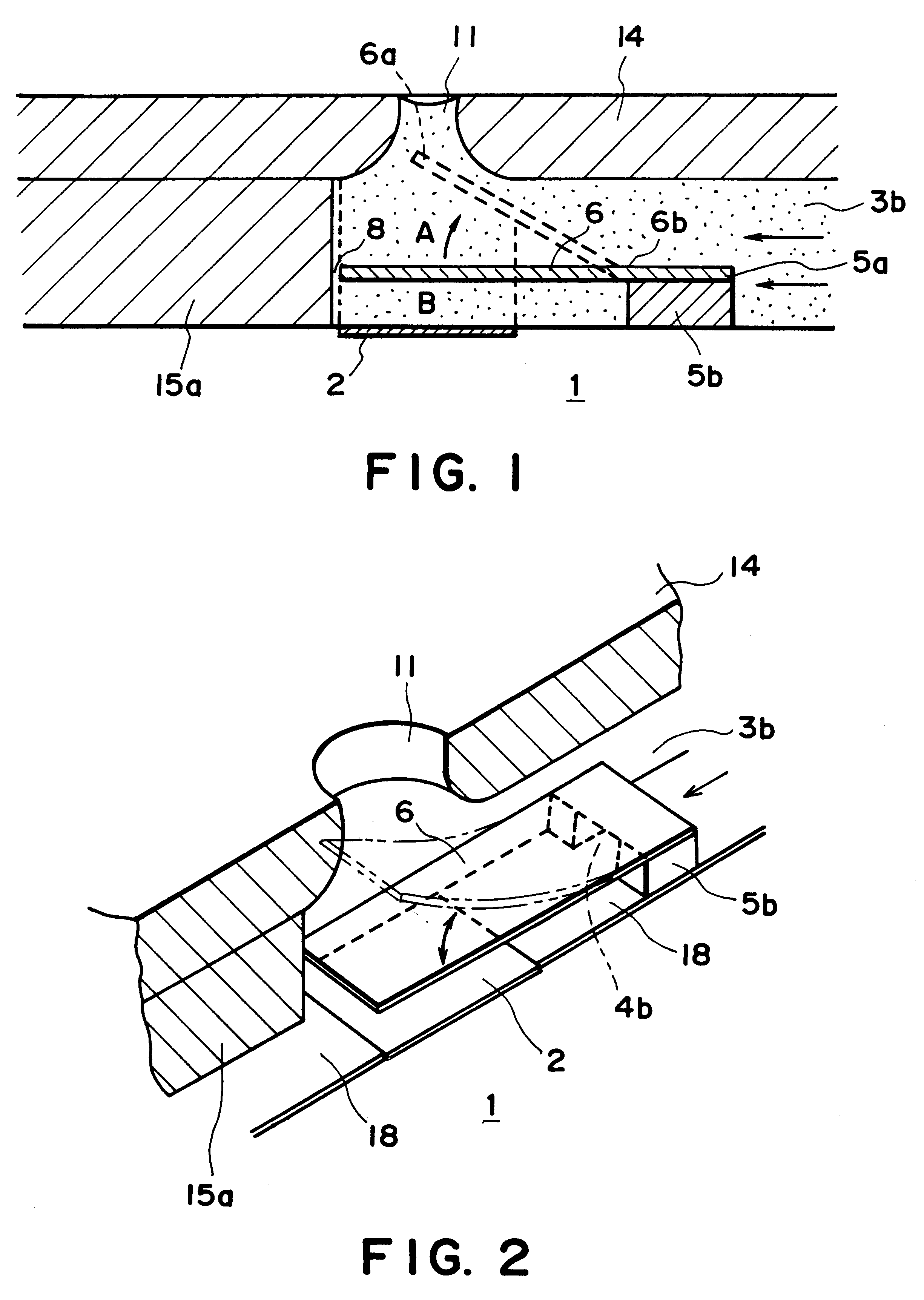
FIG. 18 is a schematic perspective view of a liquid ejecting head according to an embodiment of the present invention. The 1 of this embodiment is different from the foregoing head is in that the movable portion 6 is an independent member rather than a pair. The defect 15d having the flow passage wall 15 functions as an opposing member. In this embodiment, a liquid ejecting head with the high ejection power and high ejection efficiency, is provided.

(Movable Portion and Separation Wall)

FIG. 19A-FIG. 19C are schematic top plan views of liquid ejecting heads having a movable portions according to further embodiments. FIG. 19A shows an example, wherein the movable portion 6 of the separation wall 5 is rectangular. FIG. 19B shows an example, wherein the movable member is rectangular with narrowed base portion 6b functioning as the fulcrum upon the displacement or deflection. FIG. 19C shows an example, wherein the movable member is rectangular with wider base portion 6b fu...

first embodiment

FIGS. 24A-24E are schematic sectional drawings depicting the steps of the liquid ejection head manufacturing method in the present invention.

Referring to FIG. 24A, the electrothermal transducer comprising a heating member 2 composed of hafnium boride, tantalum nitride, and the like is formed on the element substrate 1, that is, an individually plotted section of a silicon wafer, using manufacturing apparatuses similar to those employed for the semiconductor manufacturing process. Then, the surface of the element substrate 1 is cleansed to improve its adhesiveness to the photosensitive resin which is involved in the following step. In order to further improve the adhesiveness, the properties of the element substrate surface are modified with a combination of ultraviolet rays and ozone, or the like combination, and then is spin coated with, for example, a 1 wt. % ethyl alcohol solution of silane coupler A189 (product of NIPPON UNICA).

Next, referring to FIG. 24B, a dry film Odyl SY-318...

second embodiment

FIGS. 26A-26D are schematic sectional drawings depicting the steps of the liquid ejection head manufacturing method in the present invention.

Referring to FIG. 26A, in this embodiment, a 15 .mu.m thick resist 101 is placed on a stainless steel (SUS) substrate 100, in the pattern of the second liquid flow path.

Next, referring to FIG. 26B, a nickel layer is grown on the exposed surface of the SUS substrate 100 by plating, to a thickness of 15 .mu.m, the same thickness as the thickness of the resist 101. As for the plating solution, a mixture of sulfamic acid nickel, stress reducing agent Zero Ohru (product of World Metal Inc.), boric acid, anti-pitting agent NP APS (product of World Metal Inc.), and nickel chloride, is used. As for the means for applying an electric field, an electrode is attached to the anode side, and the SUS substrate 21 on which pattering has been completed is attached to the cathode side. The temperature of the plating solution and the current density are kept at ...


PUM


Abstract

A liquid ejection head has a heat generating surface for generating heat for generating bubbles in liquid, the heat generating surface being substantially flush and/or smoothly continuous with an upstream surface of the heat generating surface, a portion above the upstream surface and a further upstream portion being in fluid communication with each other when the heat generating surface does not generate heat, a movable member having a free end and a fulcrum, the movable member and the heat generating surface having a space therebetween, and an ejection outlet for ejecting liquid through generation of the bubble. The ejection outlet opposes the heat generating surface with the movable member interposed therebetween, and an opposing member cooperates with the movable member to direct the bubble toward the ejection outlet. The movable member directs the growing bubble toward the ejection outlet in a direction substantially perpendicular to the heat generating surface.

Description

FIELD OF THE INVENTION AND RELATED ARTThe present invention relates to a liquid ejecting head for ejecting desired liquid using generation of a bubble by applying thermal energy to the liquid, a head cartridge using the liquid ejecting head, a liquid ejecting device using the same, a manufacturing method for the liquid ejecting head, a liquid ejecting method, a recording method, and a print provided using the liquid ejecting method. It further relates to an ink jet head kit containing the liquid ejection head.More particularly, it relates to a liquid ejecting head having a movable member movable by generation of a bubble, and a head cartridge using the liquid ejecting head, and liquid ejecting device using the same. It further relates to a liquid ejecting method and recording method for ejection the liquid by moving the movable member using the generation of the bubble.The present invention is applicable to equipment such as a printer, a copying machine, a facsimile machine having a...

Claims


Application Information

Patent Timeline
IPC IPC(8): B41J2/14
CPCB41J2/14048B41J2/01B41J2/175
Inventor KASHINO, TOSHIOKIMURA, MAKIKOOKAZAKI, TAKESHIYOSHIHIRA, AYAKUDO, KIYOMITSUNAKATA, YOSHIE
Owner CANON KK
Why Eureka
Try Eureka