
Apparatus and method for monitoring a system and displaying the status of the system

a technology of apparatus and system, applied in the field of apparatus and a monitoring system, can solve the problems of false warnings, and busy physicians and nurses, and achieve the effect of avoiding misdiagnosis of the system condition, avoiding false warnings, and avoiding false warnings

Inactive Publication Date: 2001-01-16
ALBERT EINSTEIN HEALTHCARE NETWORK
View PDF5 Cites 174 Cited by
  • Summary
  • Abstract
  • Description
  • Claims
  • Application Information

AI Technical Summary

Benefits of technology

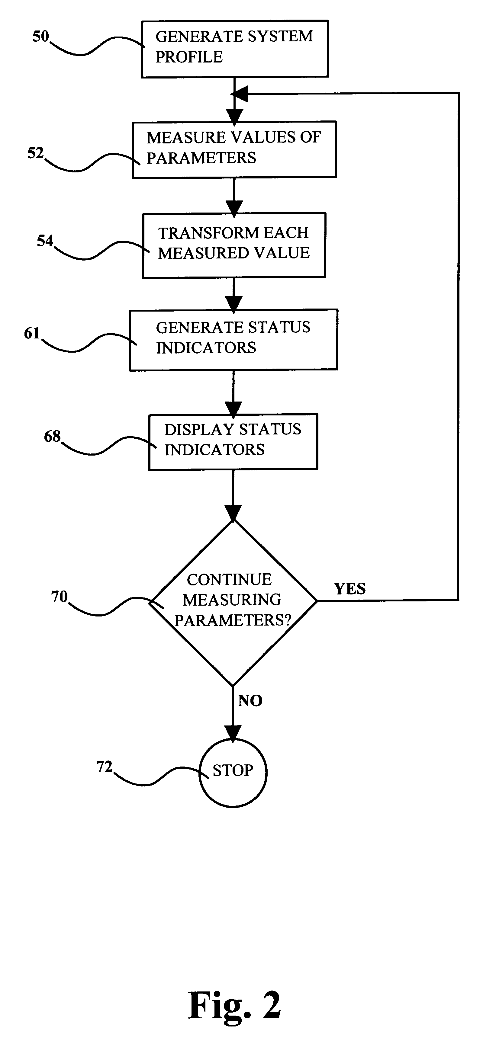
The disadvantages associated with the known apparatus and methods for monitoring systems are overcome by an apparatus and method in accordance with the present invention. According to the present invention, individual measured parameters are transformed to generate one or more status indicators. The status indicators provide a user with valuable information for assessing the overall status of the system. In addition, the status indicators can be calculated on-line, in real-time, thereby providing the user with up-to-date information so that the user may quickly respond to problems as they arise. Further, the transformation may be dependent upon individual characteristics of both the particular user and the particular system being monitored. Accordingly, the user will have an intuitive, as well as an empirical, understanding of how decisions regarding the system will influence the transformation of the system.

Problems solved by technology

Often, misdiagnosis of the condition of the system occurs because of the sheer volume of the data to be monitored.
In the noisy and congested atmosphere surrounding an operation on a patient or in the initial period after the operation when a large number of patients may be monitored by a few persons, busy physicians and nurses can miss physiological changes in the patient that are material to the well being of the patient.
As the system is extremely sensitive to small changes in each parameter about the homeostasis level of each parameter, the system can lead to false warnings.
Also, the measurement of the highest danger level can have limited usefulness as an indicator of the status of the system or patient.

Method used


Image

  • Apparatus and method for monitoring a system and displaying the status of the system
  • Apparatus and method for monitoring a system and displaying the status of the system
  • Apparatus and method for monitoring a system and displaying the status of the system

Examples


Embodiment Construction

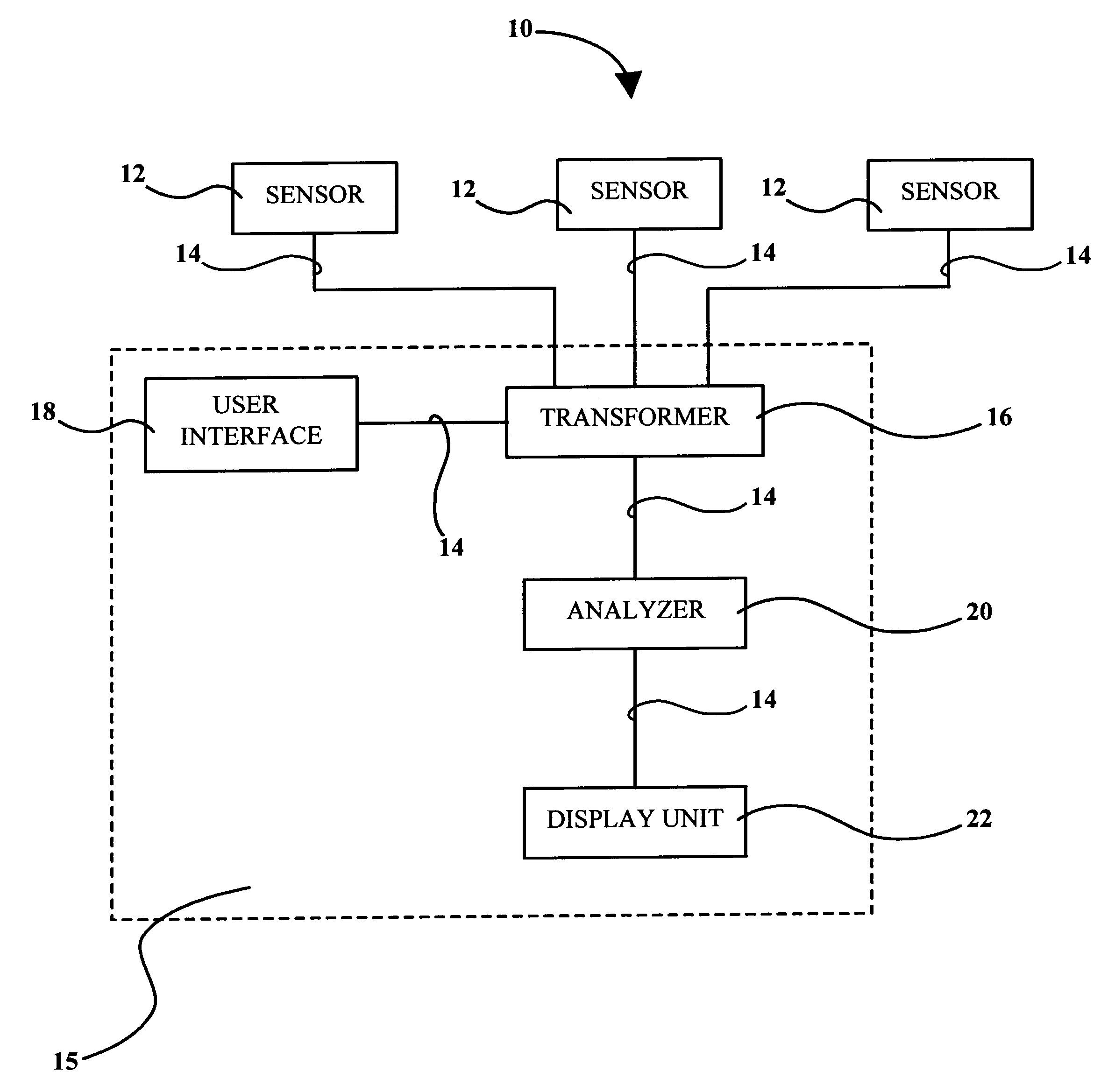
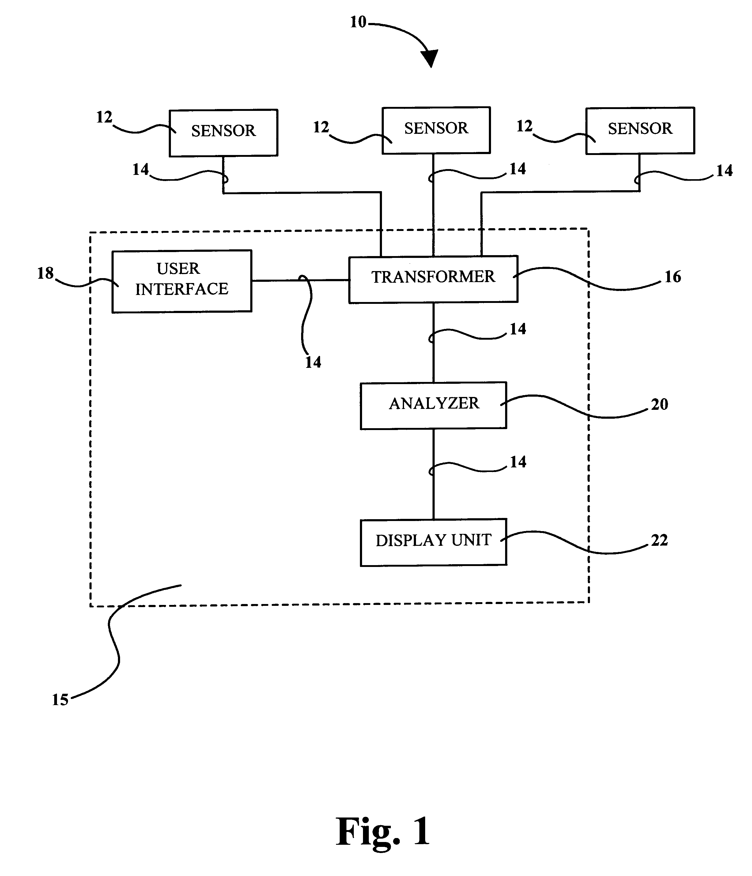
An apparatus 10 for monitoring a system in accordance with the present invention is shown schematically in FIG. 1. The apparatus 10 comprises three sensors 12 operatively connected to the system for measuring the values of three separate parameters associated with the system. However, the number and types of sensors 12 used will vary, depending upon the specific application. For example, when the status of a patient is being monitored in an operating room or intensive care setting, more than thirty different physiological parameters (e.g., heart rate, blood pressure, cardiac output, etc.) are typically measured.

The measured values of the parameters are then transferred from a sensor to a processor 15 across one or more signal lines 14. In one embodiment, the sensors 12 are interfaced to the processor 15 using an RS-232 serial multiplexer. The processor 15 can comprise a single stand-alone unit or it can be linked to a departmental network using client / server architecture. In one emb...


PUM


Abstract

An apparatus and method for monitoring a system or patient to provide information regarding the status of the system. The apparatus comprises a means of transforming measured values of more than one parameter of the system using a function dependent on at least baseline and critical values of the parameters. The apparatus further includes mapping means for mapping the function to a sequence of reference values and generating a deviation indicator for each parameter. The deviation indicators are analyzed by an analyzer to generate information concerning the status of the system or patient.

Description

FIELD OF THE INVENTIONThe present invention relates to an apparatus and a method for monitoring a system and, more specifically, to an apparatus and a method for monitoring a system to provide information regarding the status of the system.BACKGROUND OF THE INVENTIONMany industries require that vast amounts of data pertaining to a particular system be monitored and analyzed in order to make split-second assessments concerning the condition of the system. For example, physicians and anesthesiologists routinely monitor more than thirty physiological parameters (e.g., heart rate, blood pressure, cardiac output, etc.) when treating patients in intensive care units, operating rooms, and emergency rooms. Also, financial advisors and analysts in the course of their work frequently check many parameters that can influence stock prices (e.g., closing price, 52-week high and low, dividends, yield, change, previous day high and low, etc.) in order to appropriately advise their clients. Further...

Claims


Application Information

Patent Timeline
IPC IPC(8): A61B5/0205G06F19/00A61B5/00A61B5/022
CPCA61B5/0205G06F19/3406G06F19/3431G16H40/63G16H50/30
Inventor NEVO, IGALSALAH, MAHERDAGALUR, SRINIVAS S.NEWMAN, MARK
Owner ALBERT EINSTEIN HEALTHCARE NETWORK
Learn More