

Thermal imaging system
- Summary
- Abstract
- Description
- Claims
- Application Information
AI Technical Summary
Benefits of technology
Problems solved by technology
Method used
Image

Examples
Embodiment Construction
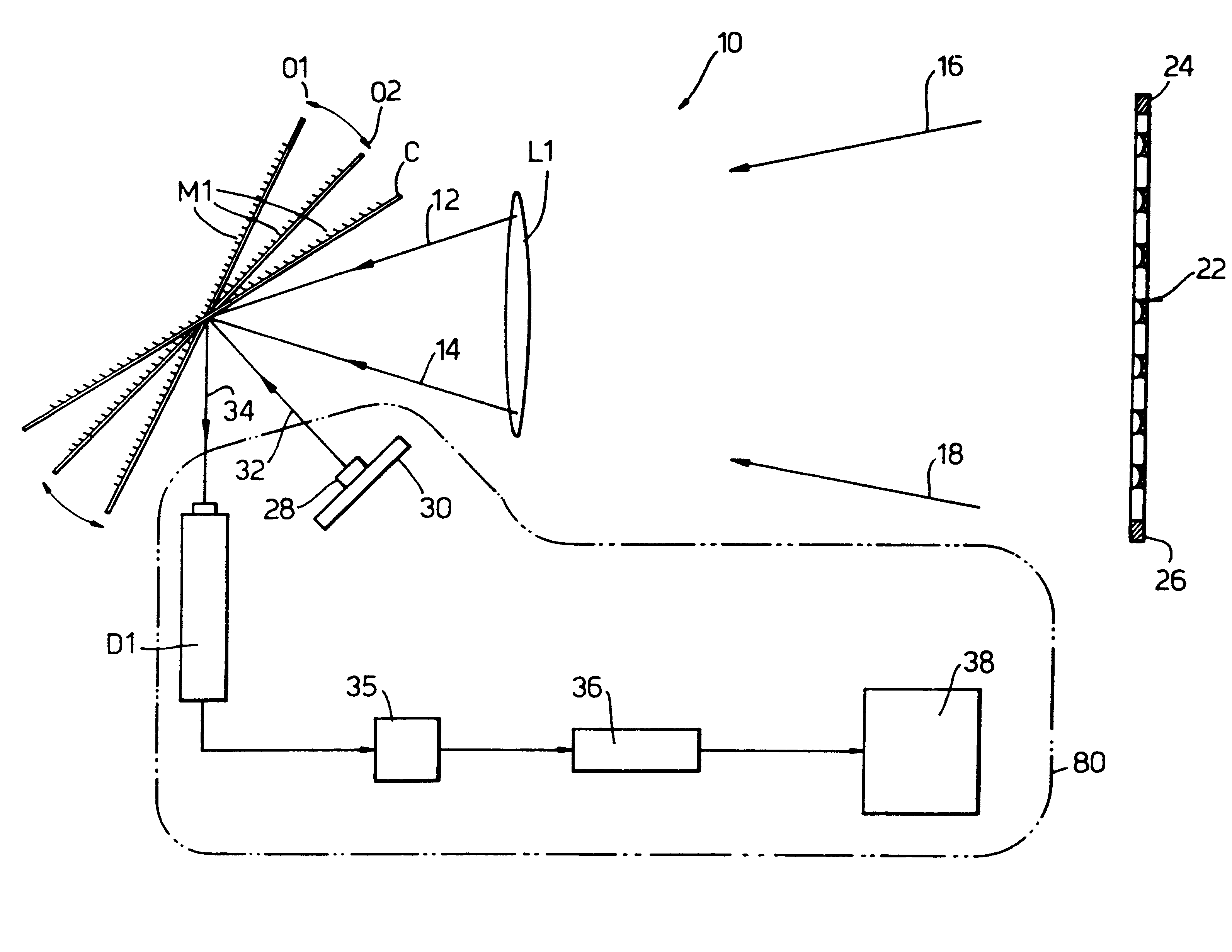
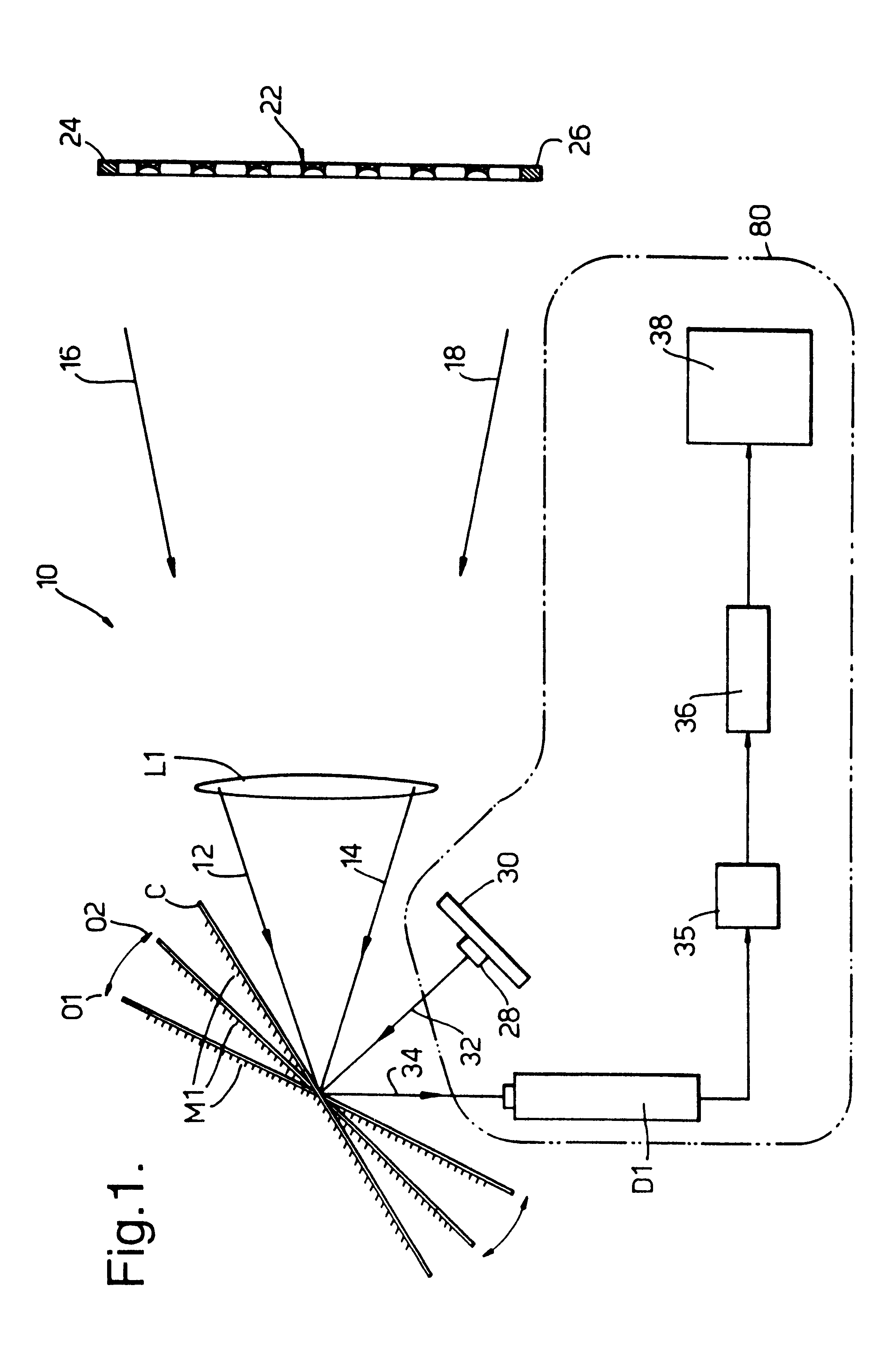
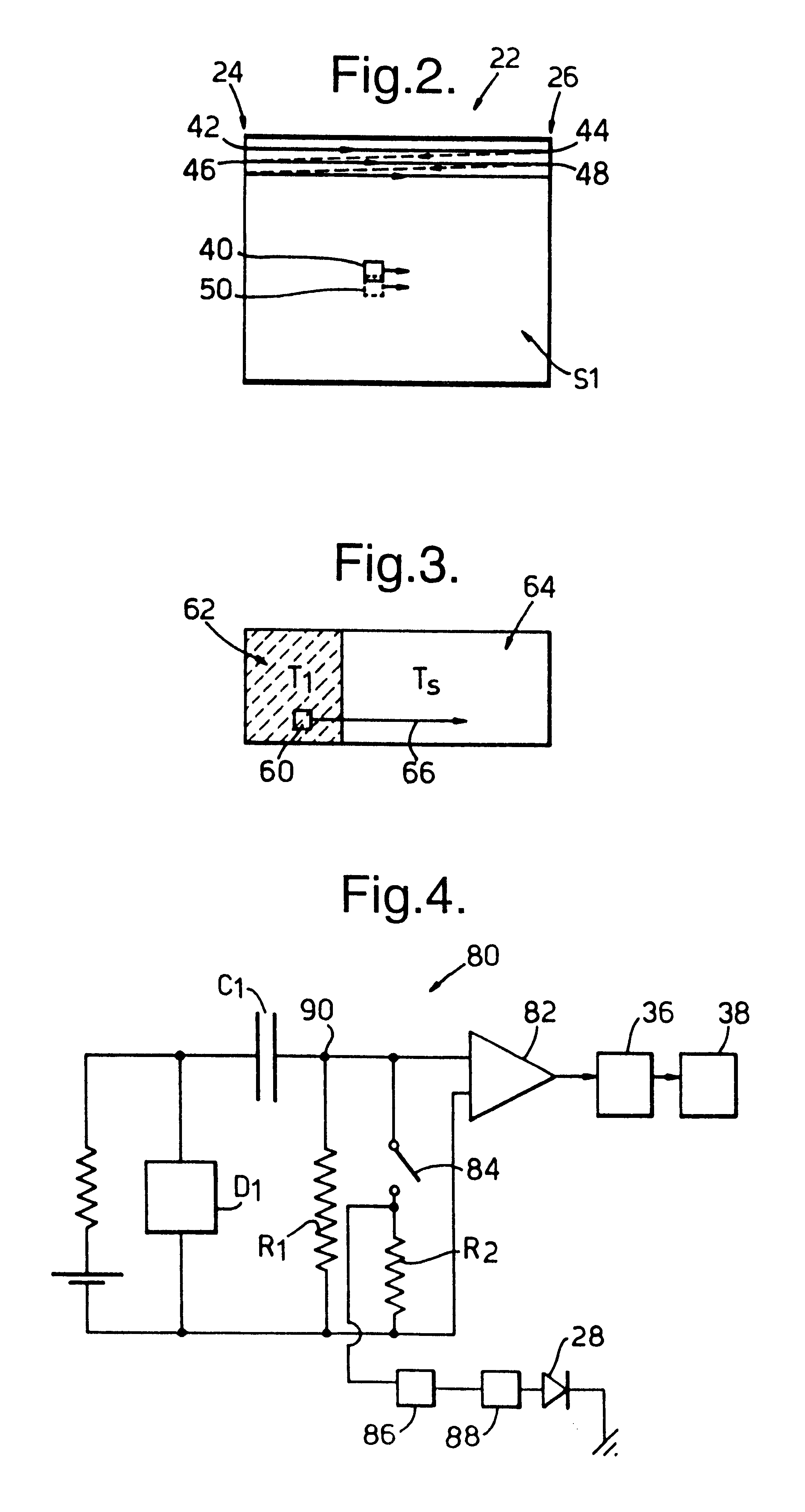
With reference to FIG. 1, there is shown a plan view of a thermal imaging system indicated generally by 10. The system 10 incorporates an objective lens L1 which focuses infrared (IR) radiation, indicated for example by rays 12 and 14 and thick arrows 16 and 18, onto an infrared photoconductive detector D1. A mirror system M1 either scans through a range of observation positions, defined in the plane of the figure by the extremities O1 and O2 (indicated by grey coloration) or shifts discontinuously to a calibration position C (black). The scanning achieved by the mirror M1 is two-dimensional although, for clarity, neither this nor a compound mirror system are shown in the diagram. A linear representation of a scene being imaged is depicted at 22 and two extreme regions are highlighted at 24, 26. An infrared light emitting diode (IRLED) 28 is mounted on a Peltier cooler / heater device 30. When the mirror M1 is in its calibration position C then IR radiation emitted by the IRLED 28 is ...
PUM
 Abstract
Description
Claims
Application Information