
Shape memory alloy-controlled slurry dispense system for CMP processing

a memory alloy and slurry dispensing technology, applied in the field of semiconductor fabrication, can solve the problems of slurry stagnation at the outer edge of the polish pad, fluid delivery system of the clamping tool, and slurry stagnation

Inactive Publication Date: 2001-01-30
ADVANCED MICRO DEVICES INC
View PDF4 Cites 14 Cited by
  • Summary
  • Abstract
  • Description
  • Claims
  • Application Information

AI Technical Summary

Problems solved by technology

There are several disadvantages associated with conventional CMP tool fluid delivery systems.
Reliance upon centrifugal force as the primary mechanism for dispersal of slurry across the polish pad surface can lead to slurry stagnation at the outer edge of the polish pad.
Slurry stagnation near the outer edge of a polish pad is also a result of a combination of other mechanisms, such as the gradual dilution of the slurry due to the radially outward flow of waste products removed from the wafer surface during polishing, and the lack of an adequate real time refreshing of slurry onto the polish pad from the fluid dispensing system.
Accordingly, in areas of the polish pad where slurry stagnation is occurring, there will be less reactants, and thus less than optimal polishing for those portions of wafer surfaces that are polished by that portion of the polish pad.
Time and slurry consumption are two other disadvantages associated with conventional CMP systems.
This cycle time and slurry consumption is a necessary though undesirable consequence of the use of a pump fed fluid delivery system in conjunction with the aforementioned dispersal cone and polish pad rotation to provide centrifugal force dispersal of the fluid across the polish pad.

Method used


Image

  • Shape memory alloy-controlled slurry dispense system for CMP processing
  • Shape memory alloy-controlled slurry dispense system for CMP processing
  • Shape memory alloy-controlled slurry dispense system for CMP processing

Examples


Embodiment Construction

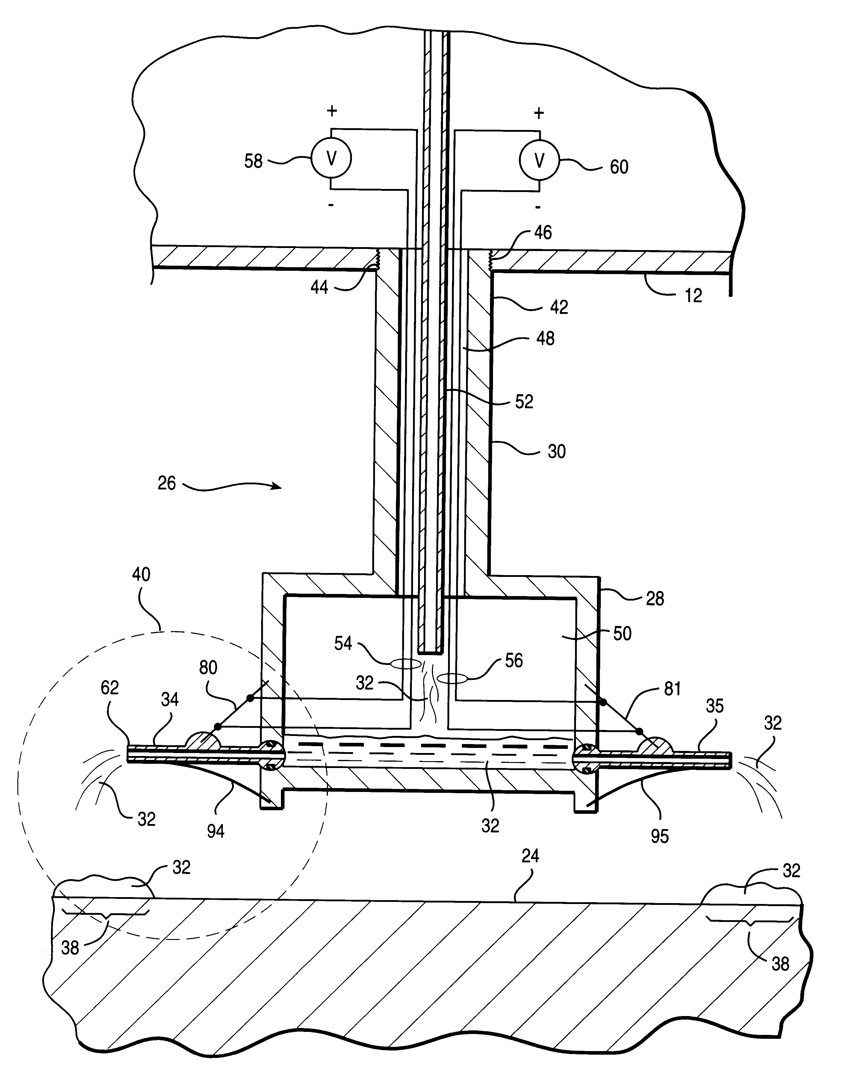
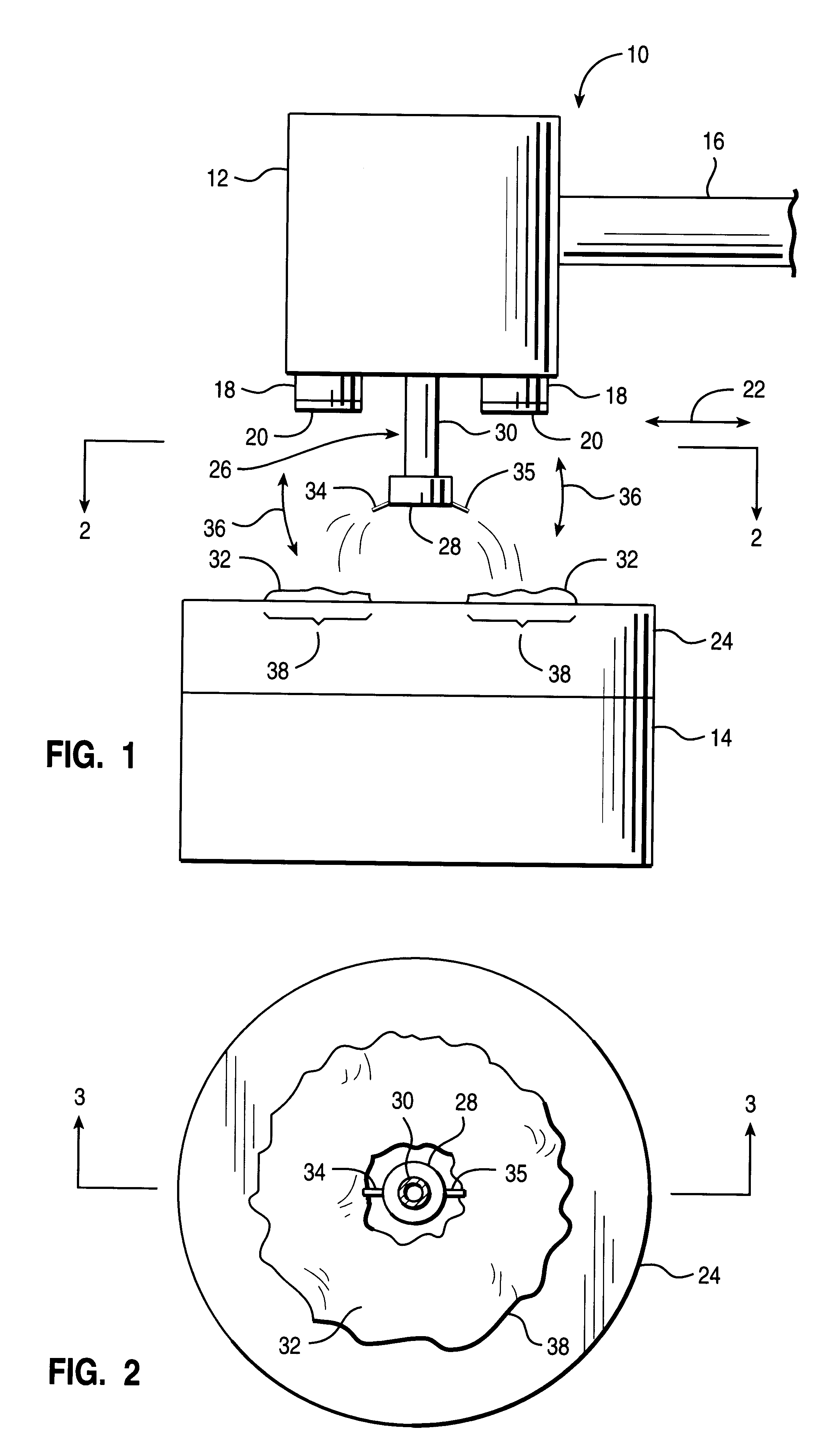
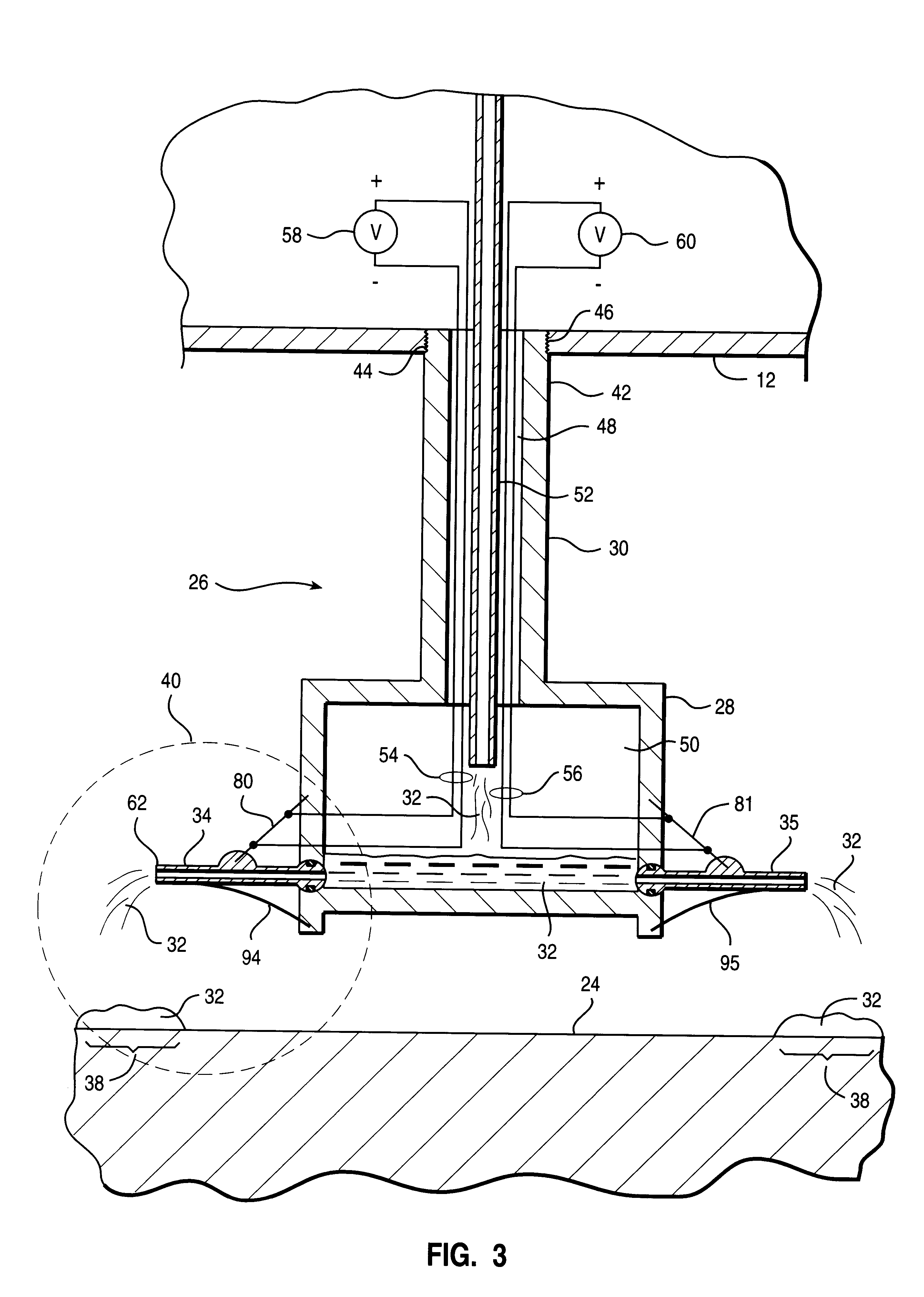
In the drawings described below, reference numerals are generally repeated where identical elements appear in more than one figure. Turning now to the drawings, FIGS. 1 and 2 illustrate, respectively, a side view and a sectional view of an exemplary embodiment of a chemical mechanical planarization ("CMP") tool 10 in accordance with the present invention. FIG. 2 is a sectional view of FIG. 1 taken at section 2--2. The CMP tool 10 includes a head assembly 12 that is positioned above a table assembly 14. The head assembly 12 is movable vertically by way of a support member 16 that is coupled thereto. The support member 16 may be operated electrically, mechanically or by fluid drive. The depiction of the support member 16 is intended to be schematic in nature as a myriad of structures may be used to support and move the head assembly 12 vertically. The head assembly 12 is provided with one or more heads 18 which are designed to manipulate semiconductor workpieces 20. The heads 18 are o...


PUM


Abstract

Various apparatus for CMP processing of workpieces are provided. In one aspect, a CMP tool is provided that includes a polish pad for polishing a workpiece and a head assembly for holding the workpiece during polishing. A fluid dispenser is also provided for dispensing a fluid to process the workpiece. The fluid dispenser has a housing and a tube coupled to the housing for dispensing a semiconductor processing fluid. The tube has a first end that is operable to move from a first elevation to a second elevation. A first shape memory member is provided that has a first end coupled to the housing and a second end coupled to the tube. The shape memory member is operable to deform in response to a thermal stimulation to selectively move the tube from the first elevation to the second elevation. The tool provides selective dispersal of processing fluids on a CMP polish pad or other processing surface is before, during and after CMP or other processes. The shape memory member actuator is simple in design and capable of hundreds of thousands or even millions of cycles. Slurry stagnation at pad edge is avoided since reliance on centrifligal force for horizontal fluid movement is reduced. Savings may be realized in both prewet time and slurry consumption.

Description

1. Field of the InventionThis invention relates generally to semiconductor fabrication, and more particularly to a CMP system and a processing fluid dispensing system therefore.2. Description of the Related ArtConventional chemical mechanical planarization ("CMP") processes involve the planarization of a surface of a wafer or workpiece through the use of an abrasive slurry and various rinses and solvents. Material removal from the workpiece surface is through a combination of abrasive action and chemical reaction. In many processes, a quantity of abrasive slurry is introduced onto a polish pad of the CMP tool and distributed across the surface thereof by means of centrifugal force. Thereafter, one or more wafers are brought into sliding contact with the polish pad for a select period of time.In many conventional CMP systems, processing fluids such as slurries, solvents and rinses are dispensed from a static dispense tube that is centrally positioned above the polish pad. The polish ...

Claims


Application Information

Patent Timeline
IPC IPC(8): B24B37/04B24B57/00B24B57/02
CPCB24B37/04B24B57/02
Inventor COSTA, MATTHEW B.
Owner ADVANCED MICRO DEVICES INC
Learn More