
Magnetomechanical electronic article surveillance marker with bias element having abrupt deactivation/magnetization characteristic

Inactive Publication Date: 2001-01-30
TYCO FIRE & SECURITY GMBH
View PDF6 Cites 36 Cited by
  • Summary
  • Abstract
  • Description
  • Claims
  • Application Information

AI Technical Summary

Benefits of technology

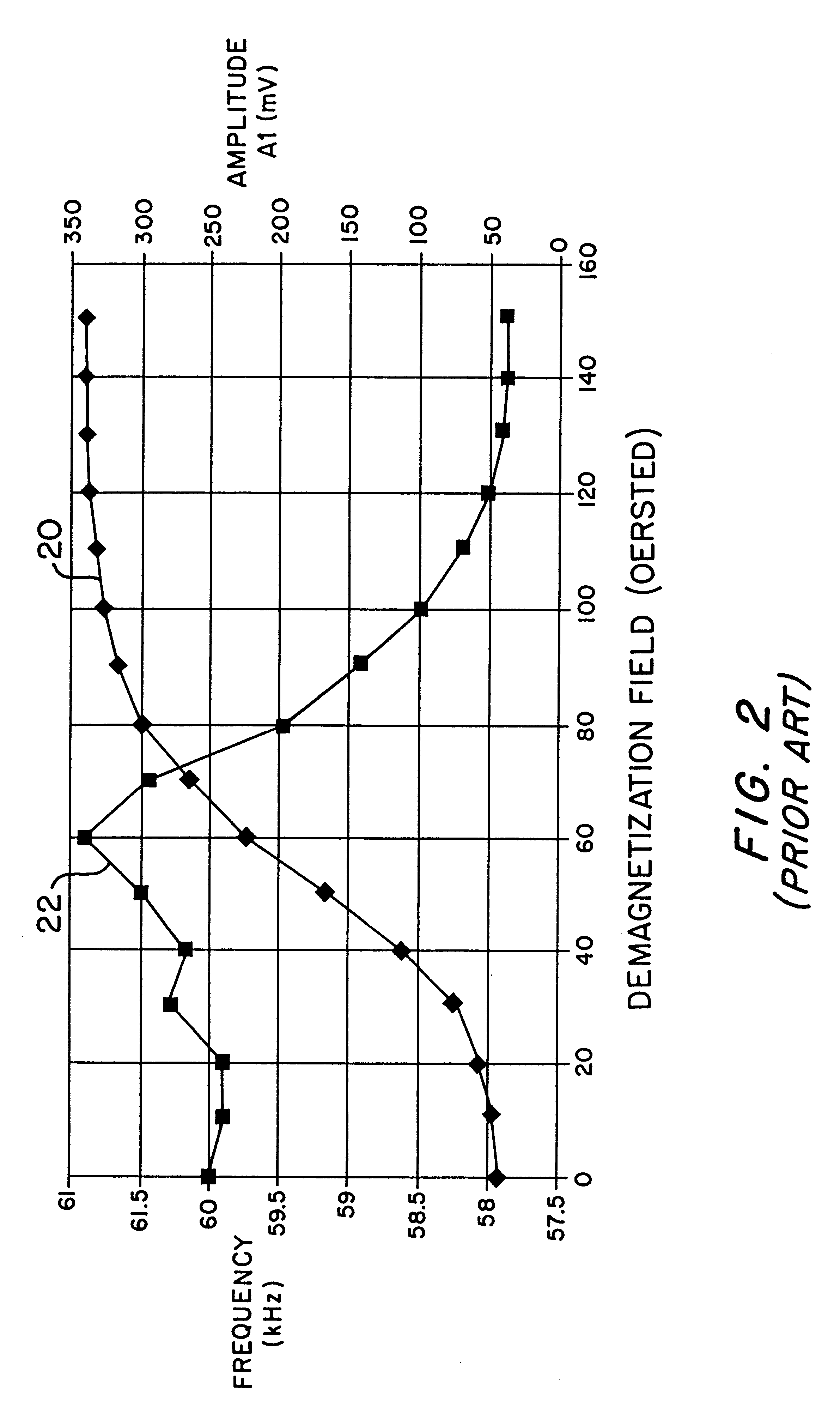
It is accordingly an object of the invention to provide a magnetomechanical EAS marker that can be deactivated by application of deactivation fields lower in strength than those required for deactivation of conventional magnetomechanical markers.
It is a further object of the invention to provide magnetomechanical markers that can be deactivated when the marker is more distant from the deactivation device than is possible with conventional magnetomechanical markers and conventional deactivation devices.
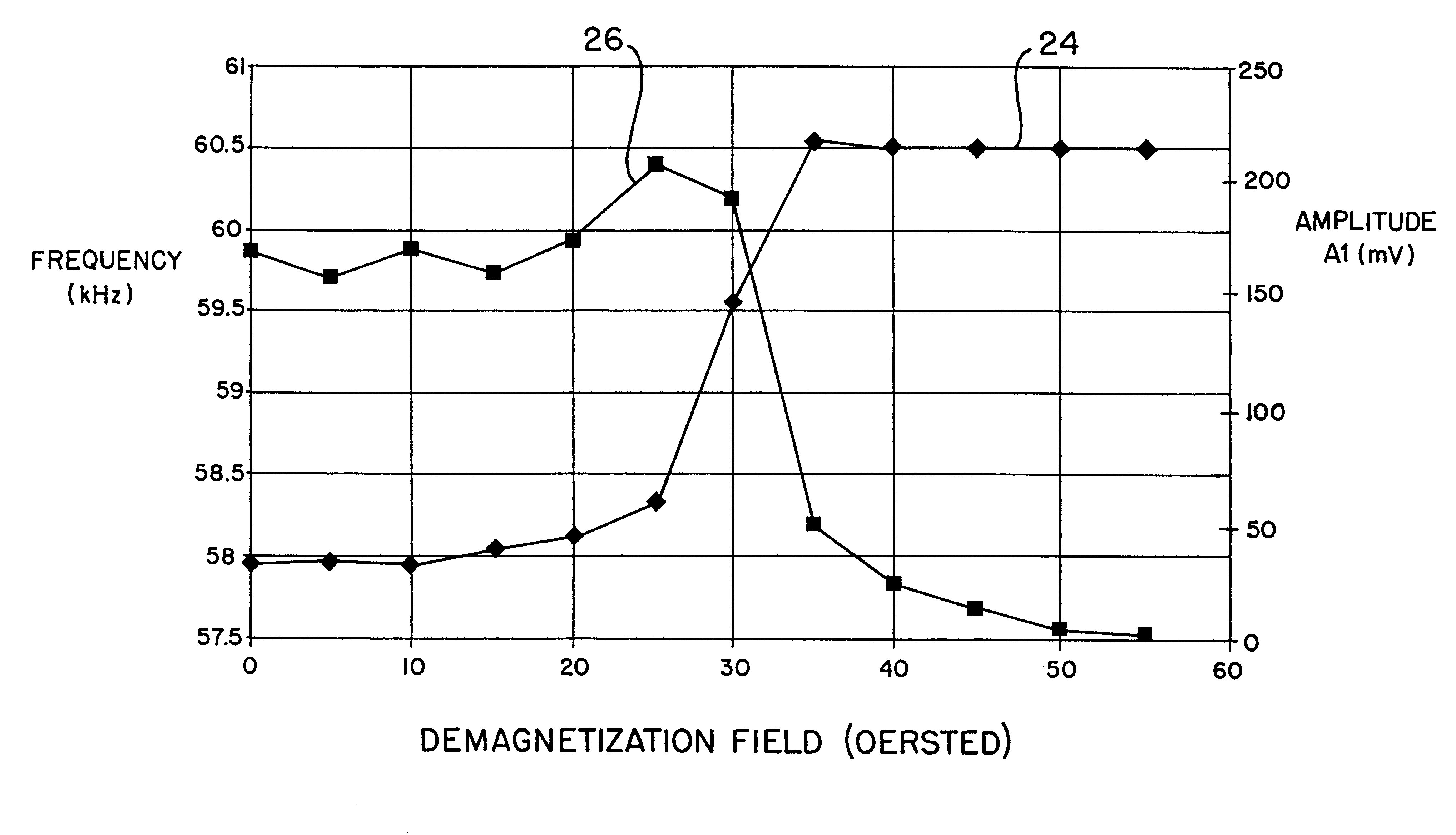
In accordance with the principles of the present invention, magnetomechanical markers are constructed using control elements that have a relatively low coercivity, and the resonant frequency of the marker can be shifted rather abruptly by application of a relatively low level AC field. Consequently, there can be a reduction in the level of field generated by marker deactivation devices and, with the lower field level, it is feasible to generate the deactivation field continuously, rather than on a pulsed basis as in conventional deactivation devices. It therefore is no longer necessary to provide marker detection circuitry in the deactivation device, nor to require an operator of the deactivation device to manually actuate a deactivation field pulse when the marker to be deactivated is placed adjacent to the deactivation device.
Furthermore, with the more easily deactivated markers formed in accordance with the principles of the invention, deactivation can be reliably performed even when the marker is at some distance, perhaps up to one foot, from the deactivation device. This capability is especially suitable for deactivation of markers that have been embedded or hidden in an article of merchandise as part of a "source tagging" program.

Problems solved by technology

The former technique places a burden on the operator of the deactivation device, and both techniques require provision of components that increase the cost of the deactivation device.
Also, even pulsed generation of the deactivation field tends to cause heating in the coil which radiates the field, and also requires that electronic components in the device be highly rated, and therefore relatively expensive.
The difficulties in assuring that a sufficiently strong deactivation field is applied to the marker are exacerbated by the increasingly popular practice of "source tagging", i.e., securing EAS markers to goods during manufacture or during packaging of the goods at a manufacturing plant or distribution facility.
In some cases, the markers may be secured to the articles of merchandise in locations which make it difficult or impossible to bring the marker into close proximity with conventional deactivation devices.

Method used


Image

  • Magnetomechanical electronic article surveillance marker with bias element having abrupt deactivation/magnetization characteristic
  • Magnetomechanical electronic article surveillance marker with bias element having abrupt deactivation/magnetization characteristic
  • Magnetomechanical electronic article surveillance marker with bias element having abrupt deactivation/magnetization characteristic

Examples


Embodiment Construction

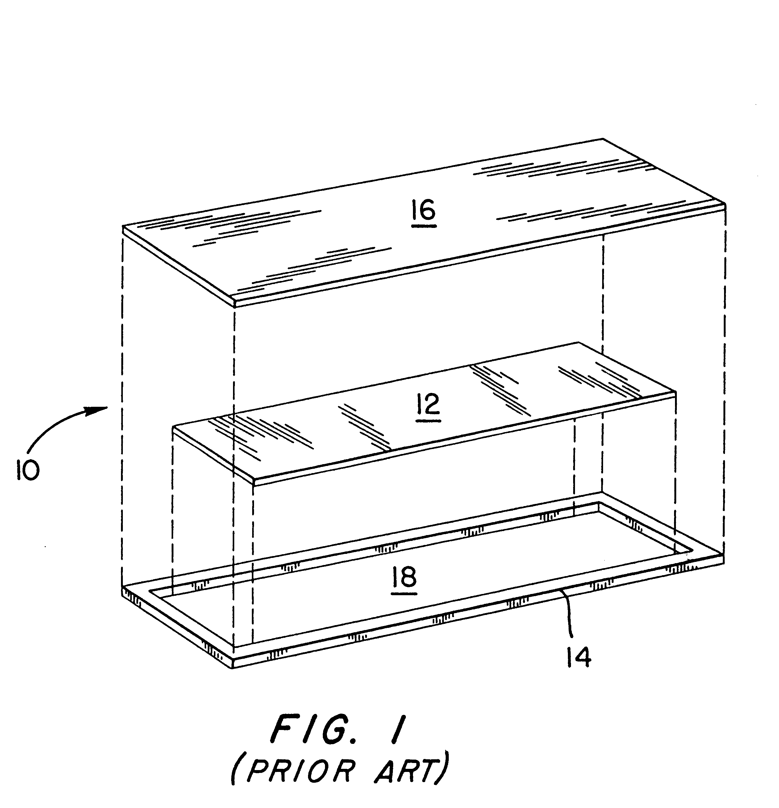
In accordance with the invention, a marker like that described above in connection with FIG. 1 is formed, using as the biasing element 16 a relatively low coercivity material such as the alloy designated as "MagnaDur 20-4" (which has a coercivity of about 20 Oe and is commercially available from Carpenter Technology Corporation, Reading, Pa), instead of the higher-coercivity conventional materials such as SemiVac 90. MagnaDur 20-4 essentially has the composition Fe.sub.77.54 Ni.sub.19.28 Cr.sub.0.19 Mn.sub.0.31 Mo.sub.2.38 Si.sub.0.30 (atomic percent). In a preferred embodiment of the invention, the active element 12 is formed from a ribbon of amorphous metal alloy designated, for example, as Metglas 2628CoA, commercially available from AlliedSignal, Inc., AlliedSignal Advanced Materials, Parsippany, N.J. Other materials exhibiting similar properties can be used for active element 12. The 2628CoA alloy has a composition of Fe.sub.32 Co.sub.18 Ni.sub.32 B.sub.13 Si.sub.5. The 2628CoA...


PUM


Abstract

A material used to form a biasing element for a magnetomechanical EAS marker has a coercivity that is lower than the coercivity of biasing elements used in conventional magnetomechanical markers. The marker formed with the low coercivity material can be deactivated by applying an AC magnetic field at a level that is lower than is required for deactivation of conventional markers. The marker with the low coercivity bias element can also be deactivated when at a greater distance from a deactivation device than was previously practical.

Description

This invention relates to magnetomechanical markers used in electronic article surveillance (EAS) systems.It is well known to provide electronic article surveillance systems to prevent or deter theft of merchandise from retail establishments. In a typical system, markers designed to interact with an electromagnetic field placed at the store exit are secured to articles of merchandise. If a marker is brought into the field or "interrogation zone", the presence of the marker is detected and an alarm is generated. Some markers of this type are intended to be removed at the checkout counter upon payment for the merchandise. Other types of markers remain attached to the merchandise but are deactivated upon checkout by a deactivation device which changes a magnetic characteristic of the marker so that the marker will no longer be detectable at the interrogation zone.A known type of EAS system employs magnetomechanical markers that include an "active" magnetostrictive element, and a biasin...

Claims


Application Information

Patent Timeline
IPC IPC(8): G08B13/24H01F1/153
CPCG08B13/2408G08B13/2411G08B13/2434G08B13/2442
Inventor COPELAND, RICHARD L.COFFEY, KEVIN R.
Owner TYCO FIRE & SECURITY GMBH
Learn More