Cooling arrangement for generator

a generator and cooling arrangement technology, applied in the direction of magnetic circuit rotating parts, vessel construction, magnetic circuit shape/form/construction, etc., can solve the problems of large increase in power generating capacity required of generator stators, common draining more electrical power than low-power generators, and insufficient capacity of 25-amp generators

Inactive Publication Date: 2001-02-06
SANSHIN KOGYO CO LTD
View PDF8 Cites 28 Cited by
  • Summary
  • Abstract
  • Description
  • Claims
  • Application Information

AI Technical Summary

Problems solved by technology

Due to the difficulties associated with cooling the generators, most conventional generators are structured for low power generating capacity.
While such structuring is suitable for some applications, engines employing the latest fuel injectors and control systems commonly drain more electrical power than the low power generators can supply.
In such instances, a 25 amp generator may not supply adequate capacity for a system designed to require as much as 45 amps of power.
Accordingly, the power generating capacity required of the stators of the generators has greatly increased while the heat generation remains a problem.
Accordingly, with the required increase in power generating capacity comes a potentially damaging increase in temperature.
An alternative to the standard rotor and stator generator is to employ a separate alternator that may be individually cooled; however, such a solution increases the bulk of the engine and results in increased weight and a greater weight distribution.

Method used


Image

  • Cooling arrangement for generator
  • Cooling arrangement for generator
  • Cooling arrangement for generator

Examples


Embodiment Construction

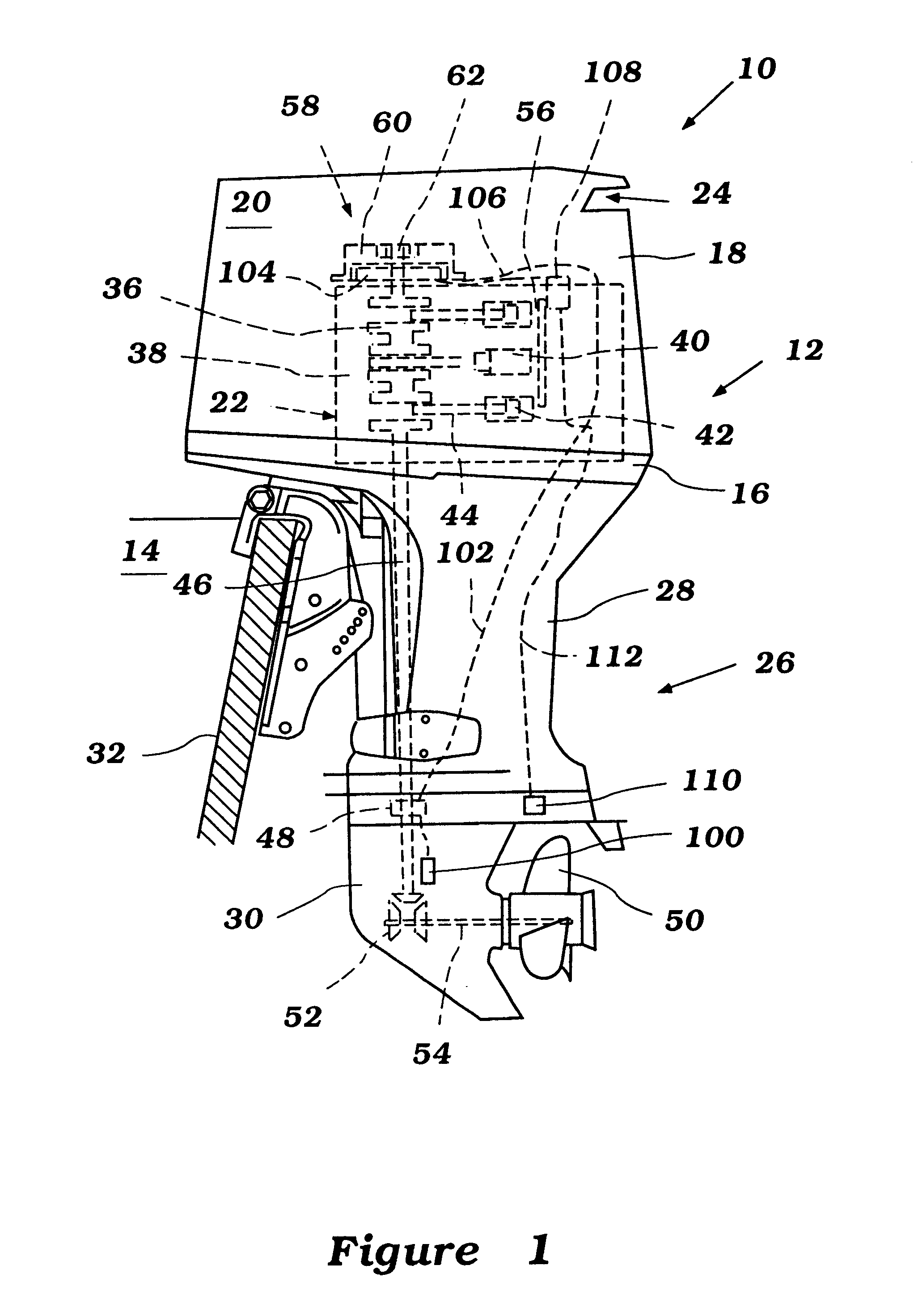
With initial reference to FIG. 1, an outboard motor for powering watercraft is illustrated. The outboard motor, indicated generally by the reference numeral 10, advantageously has a generator cooling arrangement having certain features, aspects and advantages of the present invention. The outboard motor 10 provides an exemplary environment in which the cooling arrangement has particular utility. It is anticipated, however, that the cooling arrangement may also find utility in other engine applications having liquid cooled components or air cooled components. For example, but without limitation, the present cooling arrangement may find utility with automobiles, trucks, motorcycles, watercraft, and other applications featuring an internal combustion engine powering an electrical generator. Other uses may also readily present themselves to individuals having ordinary skill in the relevant arts.

With continued reference to FIG. 1, the illustrated outboard motor 10 features a power head 1...


PUM


Abstract

An outboard motor comprises an engine contained within an engine compartment formed within a power head of the motor. The engine includes a generator having a stator and a rotor. The stator is cooled by a cooling component to reduce the operating temperature of the stator. The cooling component generally comprises a heat transfer plate or cooling jacket that is positioned adjacent to at least a portion of the stator to usher heat build-up away from the stator portion of the generator. The cooling jacket may be in fluid communication with other cooling jackets or may be a discrete system that is separate and distinct from other cooling systems of the motor.

Description

1. Field of the InventionThe present invention generally relates to electrical generator systems for engines.More specifically, the present invention relates to a cooling arrangement for such systems.2. Description of Related ArtEngines commonly employ electrical generators for powering various on-board electrical equipment. These generators, as is known, employ a rotor and a stator to create an electrical current. Specifically, as the rotor rotates within the stator, the movement creates an alternating current of electricity that is largely dependent upon the speed of the rotation. In some relevant embodiments, the stator is mounted to a housing that carries one of the bearings used to support the crankshaft. In such embodiments, the rotor is affixed to the crankshaft such that the rotor is rotated as the crankshaft turns.Due to the difficulties associated with cooling the generators, most conventional generators are structured for low power generating capacity. While such structur...

Claims


Application Information

Patent Timeline
Patent Type & Authority Patents(United States)
IPC IPC(8): F02B61/00F02B61/04H02K9/22H02K7/18B63H20/00F02B67/00
CPCF02B61/045H02K9/22H02K7/1815H02K9/223H02K9/227
Inventor OKABE, YOSHIHIKOMOTOSE, HITOSHI
Owner SANSHIN KOGYO CO LTD
Why Eureka
Try Eureka