Machine and method for unloading a bulk-material bag

a technology of bulk-material bags and machines, which is applied in the field of machines and methods for unloading bulk-material bags, can solve the problems of preventing material flow, affecting material flow, and prior art arrangements not optimally addressing the need for help, so as to reduce the distance through which the bag is unloaded, prevent bridging, and promote material flow

Inactive Publication Date: 2001-02-13
SCHENCK PROCESS LLC
View PDF12 Cites 43 Cited by
  • Summary
  • Abstract
  • Description
  • Claims
  • Application Information

AI Technical Summary

Benefits of technology

Most preferably, the first and second tri-section panels are opposite one another. Stating it another way, the first and second tri-section panels are coincident with a tri-panel axis which substantially bisects the bag laterally. In a highly preferred embodiment, the machine also includes a pair of passive support paddles pivot-mounted to be coincident with a support paddle axis generally perpendicular to the tri-panel axis. As further explained below, these support paddles reduce the distance through which the bag is required to be lifted when mounting it to or demounting it from the machine and help promote material flow.
Other aspects of the invention involve a method for unloading a bag containing bulk material and having a spout, and the bottom, side and transition portions mentioned above. The method includes providing a machine having a movable tri-section panel with first, second and third segments and suspending the bag so that its bottom, transition and side portions are proximate the first, second and third segments, respectively. The spout is opened to permit material to flow out of the bag and, sequentially, the first and second segments are urged against the bottom portion and the transition portion, respectively. This helps prevent bridging at the onset of material flow from a full bag.

Problems solved by technology

While such formation is structurally quite weak, it is sufficient to impede material flow.
This, too, impedes material flow.
While these prior art arrangements have been generally satisfactory for their intended purposes, they are not without disadvantages.
As a general observation, such prior art arrangements seem not to optimally address the need to help assure smooth powder flow during all phases of bag emptying, i.e., at initial discharge, when the bag is about half empty and when the bag is nearly empty.
More specifically, known prior art arrangements do not optimally prevent close-to-the-spout material bridging at the onset of material flow from a fully-filled bag.
Nor do such arrangements optimally prevent bridging and rat-holing well upward in the bag as emptying progresses.
And such arrangements have not fully recognized how to deal with the tendency of material to lodge in the bag lower portions when the bag is nearly, but not entirely, empty.
A difficulty with the aforedescribed bag tensioning or bag lifting mechanism is that the gas springs sometimes tend to bind.

Method used


Image

  • Machine and method for unloading a bulk-material bag
  • Machine and method for unloading a bulk-material bag
  • Machine and method for unloading a bulk-material bag

Examples


Embodiment Construction

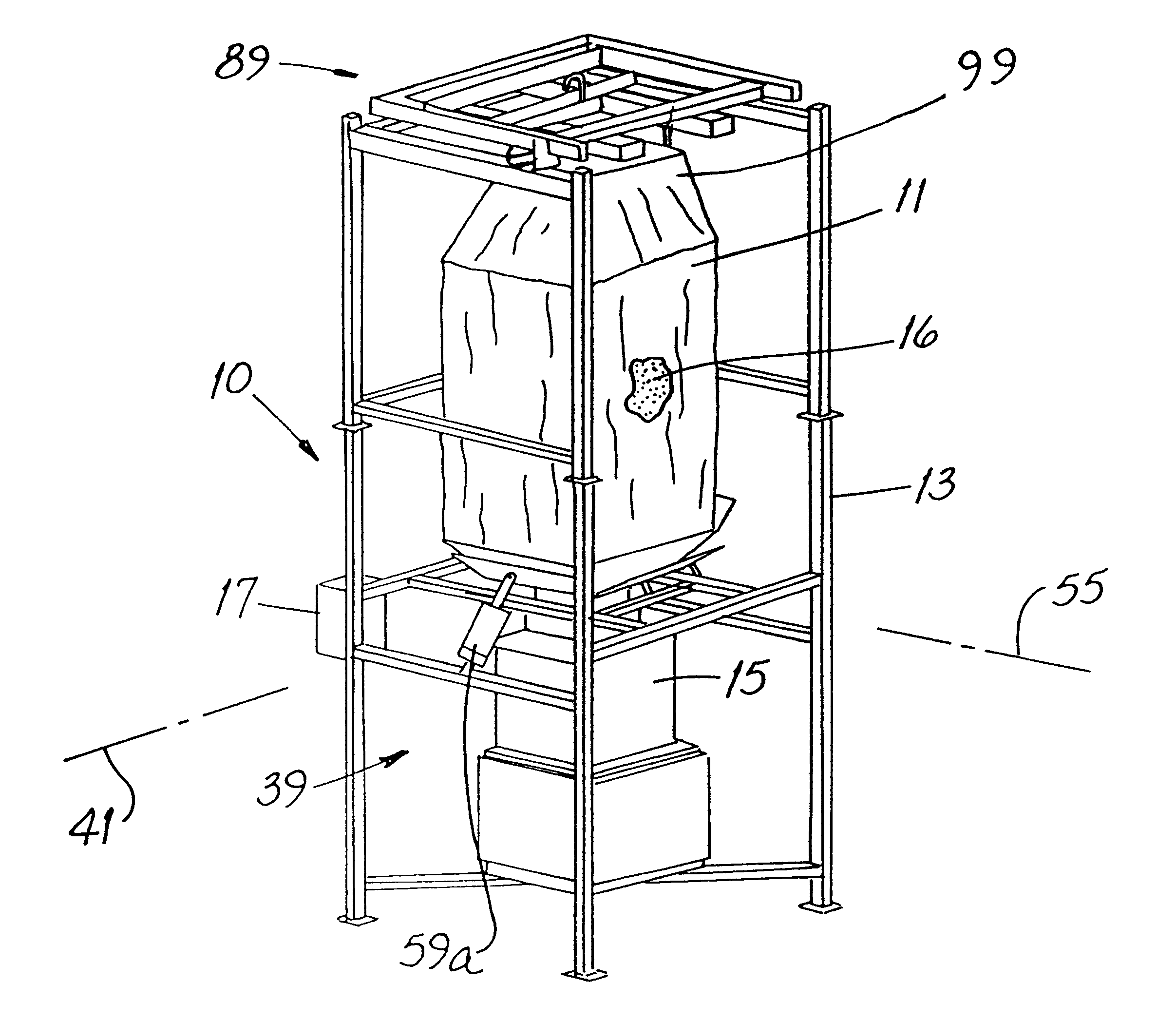
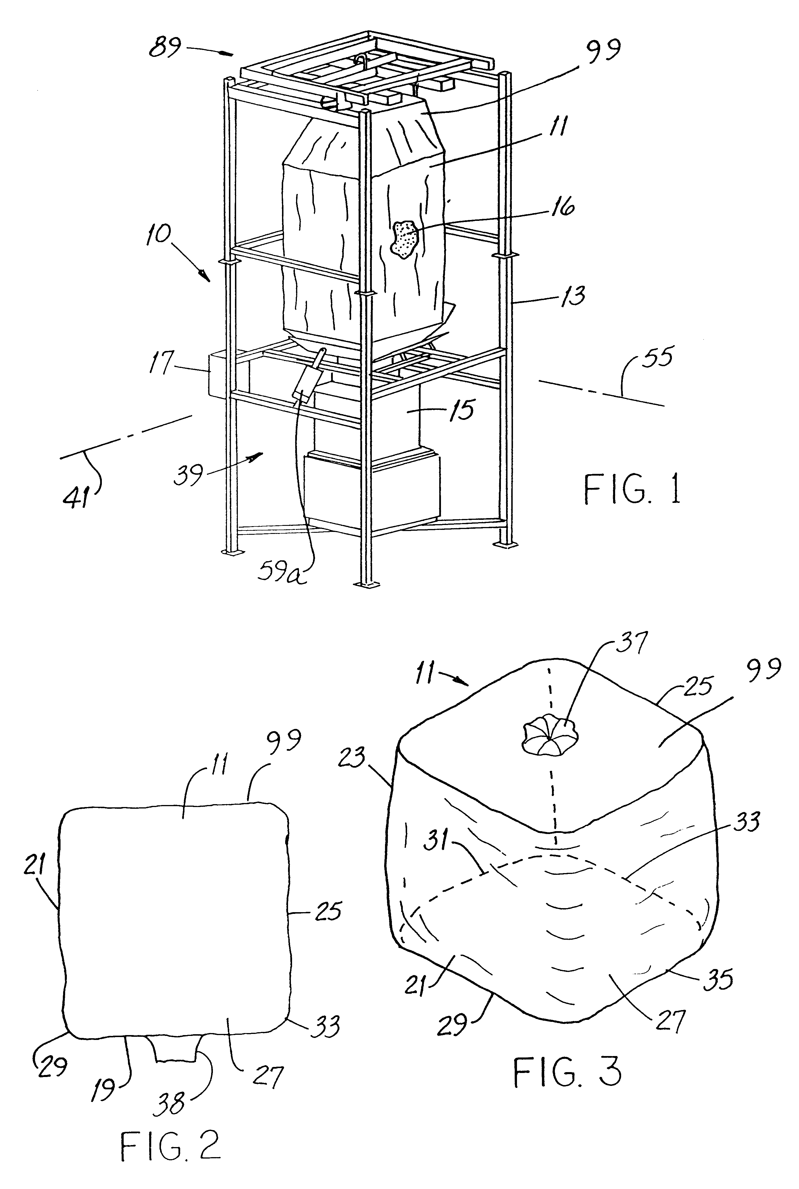
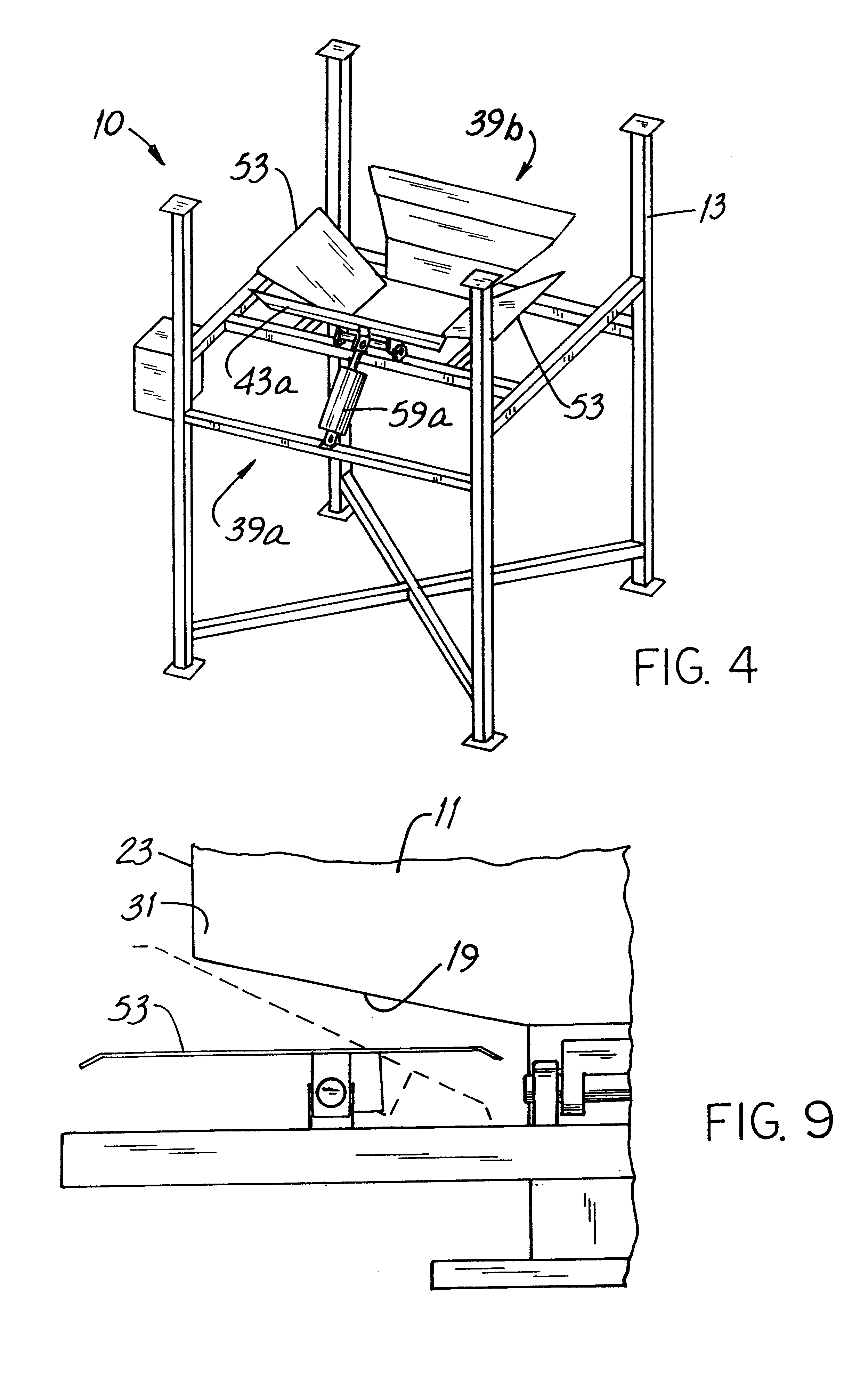
Referring to FIGS. 1, 2, 3 and 4, the invention involves improvements in a machine 10 for unloading a bulk-material bag 11. Exemplary materials, one of which might be contained in the bag 11 includes flour, rice hulls, pharmaceuticals, plastic, colorant and cement.

The machine 10 includes an upright, generally rectangular frame 13 having a receptacle 15 mounted in the lower portion thereof. Such receptacle 15 may be, for example, a screw feeder, a receiving hopper or the end of a weigh belt of the type which weighs the material thereon. A microprocessor-based process controller 17 is conveniently mounted on the frame 13.

An exemplary bag 11 is of the type having a bottom portion 19 and first, second, third and fourth side portions 21, 23, 25, 27, respectively. First, second, third and fourth transition portions 29, 31, 33, 35, respectively, extend between the bottom portion 19 and the correspondingly-numbered side portions. The bag 11 also includes a top fill port 37 and a bottom spou...


PUM


Abstract

Disclosed is a machine for unloading a bulk-material bag of the type having a bottom portion, a side portion and a transition portion between the bottom and side portions. The machine includes an apparatus aiding discharge of the material from the bag. In the improvement, the apparatus includes a tri-section panel mounted for movement on the machine, thereby configuring the panel to sequentially contact the bottom, transition and side portions of the bag. The panel has first, second and third segments angle-mounted to one another. In a specific embodiment, the segments are substantially planar. A microprocessor-based controller is coupled to the actuator and regulates its movement as a function of a process parameter, e.g., the compressibility of the bag and/or the weight of the material contained in the bag. A highly preferred embodiment of the machine also has a bag lifting mechanism above the tri-section panel. Such mechanism includes an extensible device coupled to the controller for regulating extension of such device as a function of the weight, volume or level of the material contained in the bag. A new method for unloading a bulk material bag is also disclosed.

Description

This invention relates generally to bulk material handling and, more particularly, to apparatus for emptying portable receptacles, e.g., flaccid / limp / soft-sided bags, by "jarring" or "working" them.Many types of dry, finely-divided (i.e., powdered or powder-like) materials, e.g., flour, rice hulls, pharmaceuticals, plastic, colorant, cement among many, many others, are shipped to a point of usage using large, soft-sided, reusable bags. Such bags, commonly cubic, have a top fill opening and a bottom spout and after being emptied, the soft bags may be collapsed to but a fraction of their filled volume for return to a filling site.At the point of usage, such bags are mounted one-at-a-time on a machine of the type generally known as a bag unloader or bag frame. There, the contents of the bag are emptied through the spout for, e.g., repackaging into retail containers, compacting into tablet form, mixing with other constituents or for other, further processing. A representative list of co...

Claims


Application Information

Patent Timeline
Patent Type & Authority Patents(United States)
IPC IPC(8): B65B69/00
CPCB65B69/0091
Inventor BECKER, STEVEN L.KELLY, THOMAS G.NAUMAN, JEFFREY M.
Owner SCHENCK PROCESS LLC
Why Eureka
Try Eureka