Burner for fluidic fuels having multiple groups of vortex generating elements

a technology of vortex elements and burners, which is applied in the direction of machines/engines, combustion types, lighting and heating apparatus, etc., can solve the problems of achieve small pressure loss caused by vortex elements, improve the spatial homogeneity of mixtures, and reduce the effect of mixing combustion air and fuel

Inactive Publication Date: 2001-02-20
SIEMENS AG
View PDF12 Cites 26 Cited by
  • Summary
  • Abstract
  • Description
  • Claims
  • Application Information

AI Technical Summary

Benefits of technology

An essential advantage of the invention lies in the fact that especially effective mixing of combustion air and fuel can be achieved by the turbulent flow of the combustion air, while at the same time a pressure loss caused by the vortex element is slight. Improved spatial homogeneity of the mixture is achieved by the mixing of fuel and combustion air in the turbulent flow. In addition, the variation in the mixture ratio with time has been determined in extensive tests for the first time. Locally occurring variations in the mixture ratio with time, as well as the spatial inhomogeneity, lead to a distribution of the flame temperature having the adverse effects on the nitrous-oxide emission which are explained above. The results of the tests showed that the fuel / air mixture produced exhibits a slight variation in ratio with time. Thus mixing of fuel and air which is largely homogeneous spatially and with time and thus reduced nitrous-oxide production are achieved. The pressure loss, which at the same time is only slight, leaves the efficiency of the burner virtually unaffected. This constitutes a considerable improvement over previously used vortex elements which were constructed as obtuse flow obstacles. Such flow obstacles result in a considerable pressure loss, so that improved mixing of fuel and combustion air had to be paid for with a markedly reduced efficiency of the burner.
In order to avoid flame stabilization at the vortex element, the fuel is admitted on the downstream side of the vortex element. Thus only combustion air flows through the vortex element, and the risk of combustion in the region of the vortex element, which could damage the latter, is reduced.
In accordance with a further feature of the invention, the vortex element is constructed in such a way that the turbulent flow of combustion air which can be generated at the vortex element has essentially no zones of backflowing combustion air. Thus a situation is achieved in which no ignitable fuel / air mixture can flow back to the vortex element and thus combustion, which could damage the vortex element, is not stabilized at the latter.
In accordance with an added feature of the invention, the turbulent flow of combustion air which can be generated has vortices of a diameter comparable to the width of the air duct, in particular a diameter of 20-80% of the width of the air duct. This configuration achieves a situation in which the region of the fuel inlet can be completely covered by a vortex and the turbulent flow extends beyond the region of the fuel inlet, so that mixing is effected both in the vortex at the fuel inlet and in the turbulent flow behind the fuel inlet, with the effect of especially intensive intermixing.
In accordance with an additional feature of the invention, there are provided swirl blades disposed in the air duct on the downstream side of the vortex element. In this way, a vortex element having the advantageous effects described above on the homogeneity of the mixing of fuel and combustion air is used in combination with swirl blades, which have a favorable effect on the stability of the combustion.
In accordance with yet another feature of the invention, at least one of the swirl blades is constructed as a hollow blade from which the fuel can be admitted. It is possible with this configuration to utilize a uniform injection of fuel from a swirl blade, constructed as a hollow blade and having a further homogenizing effect on the fuel / air mixture, in combination with the advantages explained above.

Problems solved by technology

A burner having such a vortex element has an especially small pressure lose caused by the vortex element.

Method used


Image

  • Burner for fluidic fuels having multiple groups of vortex generating elements
  • Burner for fluidic fuels having multiple groups of vortex generating elements
  • Burner for fluidic fuels having multiple groups of vortex generating elements

Examples


Embodiment Construction

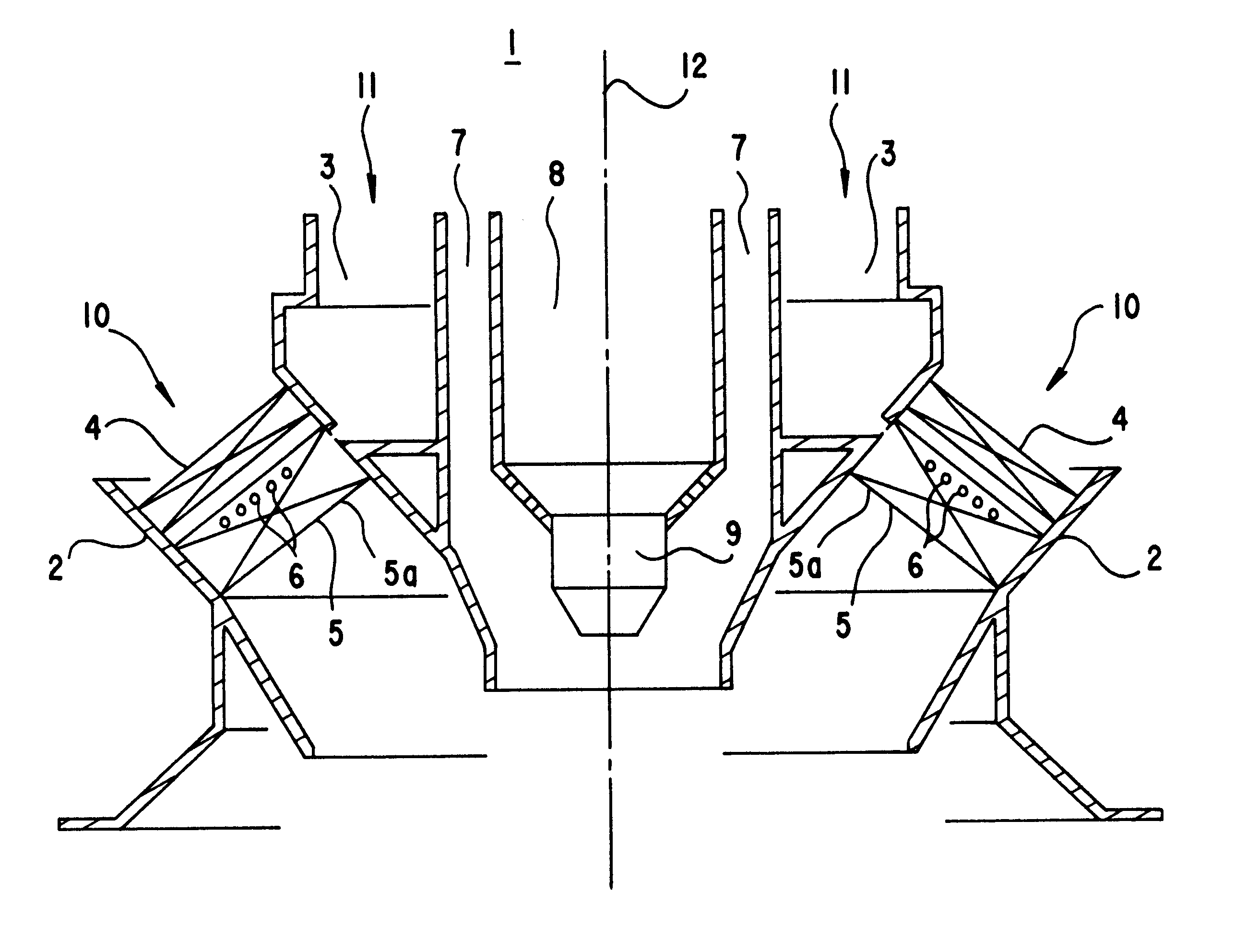
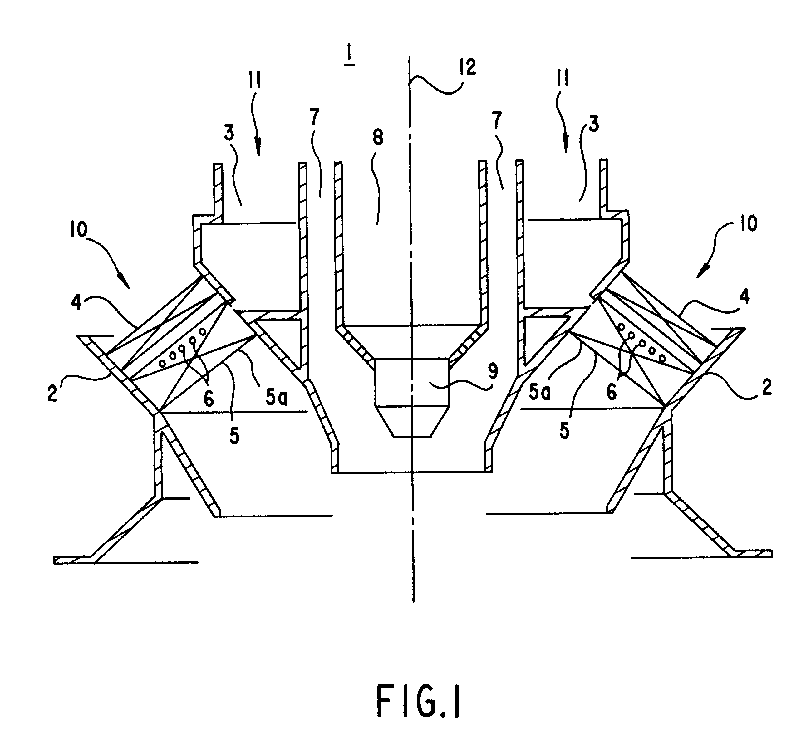
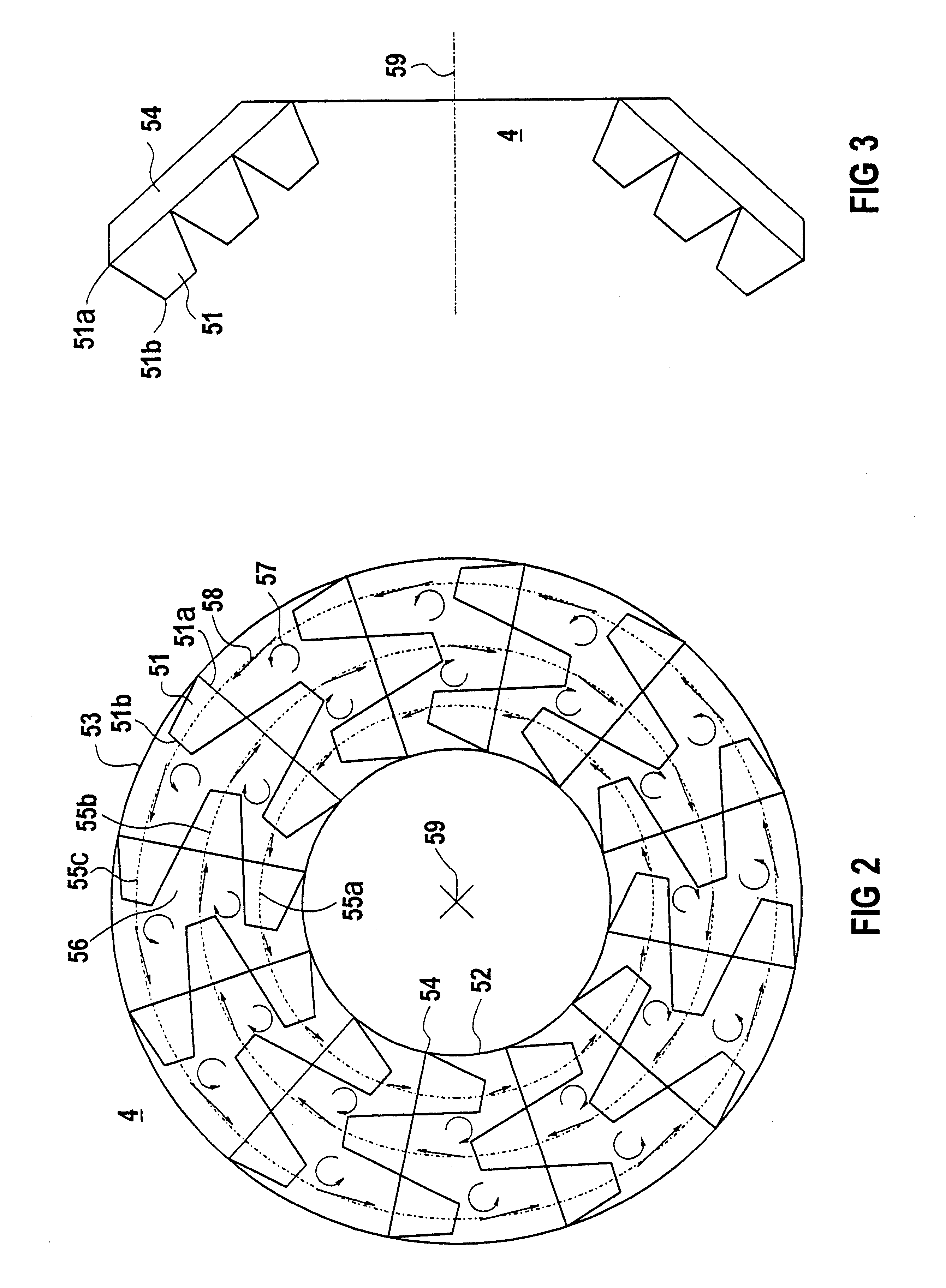
Referring now to the figures of the drawings in detail and first, particularly, to FIG. 1 thereof, there is seen a hybrid burner 1, which is approximately rotationally symmetrical with regard to an axis 12. A pilot burner 9, which is directed along the axis 12 and has a fuel-feed duct 8 and an annular air-feed duct 7 concentrically enclosing the latter, is concentrically surrounded by an annular fuel duct 3. This annular fuel duct 3 is enclosed at the bottom, i.e. partly concentrically, by an annular air-feed duct 2. A swirl blade ring 5, which is shown diagrammatically, is fitted in this annular air-feed duct 2. At least one of these swirl blades 5 is constructed as a hollow blade 5a. The hollow blade 5a has an inlet 6 which is formed by a plurality of openings and is intended for a fuel feed. The annular fuel duct 3 leads into this hollow blade 5a. A diagrammatically illustrated vortex element 4 is fitted in the air duct 2 on the inflow side of the swirl-blade ring 5.

The hybrid bu...


PUM


Abstract

A burner, in particular for a gas turbine, in which combustion air is subjected to a vorticity by a vortex element, admits fuel to the vortical combustion air. At the same time, a pressure loss produced by the vortex element is small. A low NO.sub.x emission at virtually the same efficiency is achieved.

Description

BACKGROUND OF THE INVENTIONField of the InventionThe invention relates to a burner for fluidic fuels, in particular for use in a gas-turbine plant.A burner for fluidic fuels, which is used in particular in a gas-turbine plant, has been disclosed by German Published, Non-Prosecuted Patent Application DE 42 12 810 A1. It is apparent from that publication that air is fed through an annular air-feed-duct system and fuel is fed through a further annular-duct system to the combustion. In that case, fuel is injected from the fuel duct into the air duct, either directly or from swirl blades constructed as hollow blades.The intention is thus to achieve, inter alia, a homogeneous mixing of fuel and air as far as possible in order to achieve combustion having a low concentration of nitrous oxides. It is an essential requirement for combustion, in particular for combustion in the gas-turbine plant of a power station, to achieve as low a production of nitrous oxides as possible, for reasons of e...

Claims


Application Information

Patent Timeline
Patent Type & Authority Patents(United States)
IPC IPC(8): F23D14/02F23D17/00F23R3/14F23R3/04F23R3/30B01F5/00B01F5/06F23D11/12F23D14/62
CPCF23D14/02F23D17/00F23R3/14F23C2900/07001F23D2206/10F23D2900/00008
Inventor POESCHL, GERWIGHOFFMANN, STEFANGANZMANN, INGO
Owner SIEMENS AG
Why Eureka
Try Eureka