Continuous heat treating furnace and atmosphere control method and cooling method in continuous heat treating furnace

a technology of heat treatment furnace and control method, which is applied in the direction of heat treatment apparatus, drying machines with progressive movement, furnaces, etc., can solve the problems of high risk, low cooling rate of gas jet cooling method, and worsening consumption of atmospheric gas

Inactive Publication Date: 2001-02-20
JFEENG CORP
View PDF10 Cites 15 Cited by
  • Summary
  • Abstract
  • Description
  • Claims
  • Application Information

AI Technical Summary

Problems solved by technology

However, the gas jet cooling method has a drawback of low cooling rate.
This risk is particularly large under heat treatment condition of high passing speed.
In (A) and (C), a consumption of atmospheric gas is worsened, since the flow rate of the sealing gas has always to be kept and, in addition, a gas flow rate at high accuracy is necessary for ensuring the sealing performance, to make the facility expensive.
The dynamic pressure thus generated is interrupted by the roll-sealing devices to result in elevation of a static pressure in the vicinity of the roll-sealing devices.
It is necessary to increase the amount of the HN gas at a high hydrogen concentration to be charged in order to compensate the lowering of the hydrogen concentration in the rapid cooling zone, which results in worsening of the RN gas consumption.
After all, provision of a strong sealing device in order to prevent the gas flow leads to an unintentional result of inducing the gas flow due to the distribution of the furnace pressure (atmospheric pressure inside the furnace).
Such problems are not taken into consideration in existent sealing means.
Namely, it has been obtained such a finding that if the hydrogen concentration in the furnace zone in adjacent with the inlet of the rapid cooling zone is increased to higher than 10%, nitridation proceeds at the surface layer of the strip material in a state of a high temperature before rapid cooling, resulting in a problem of causing partial hardening to the surface layer.

Method used


Image

  • Continuous heat treating furnace and atmosphere control method and cooling method in continuous heat treating furnace
  • Continuous heat treating furnace and atmosphere control method and cooling method in continuous heat treating furnace
  • Continuous heat treating furnace and atmosphere control method and cooling method in continuous heat treating furnace

Examples


example 4

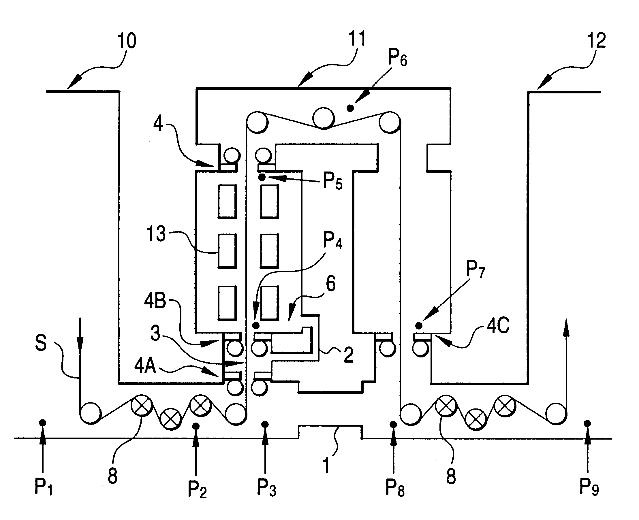
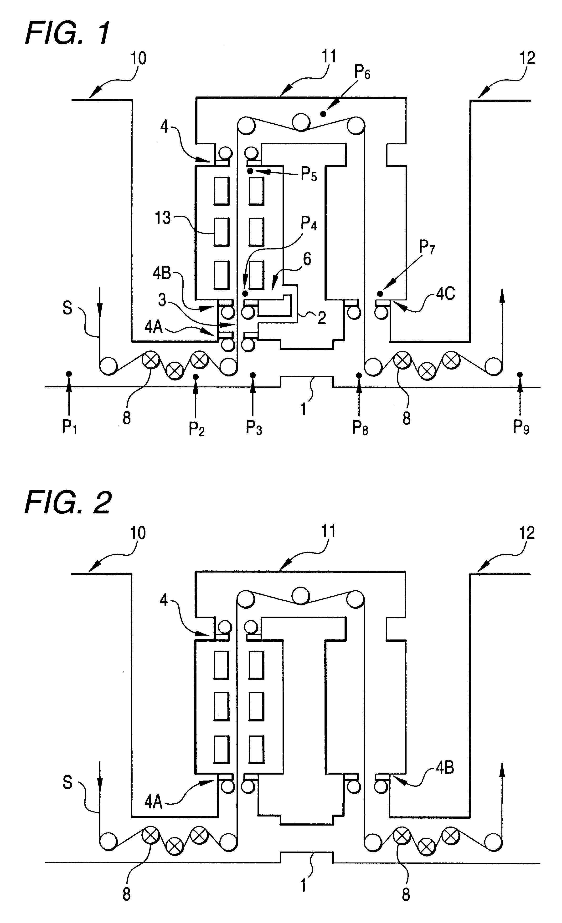
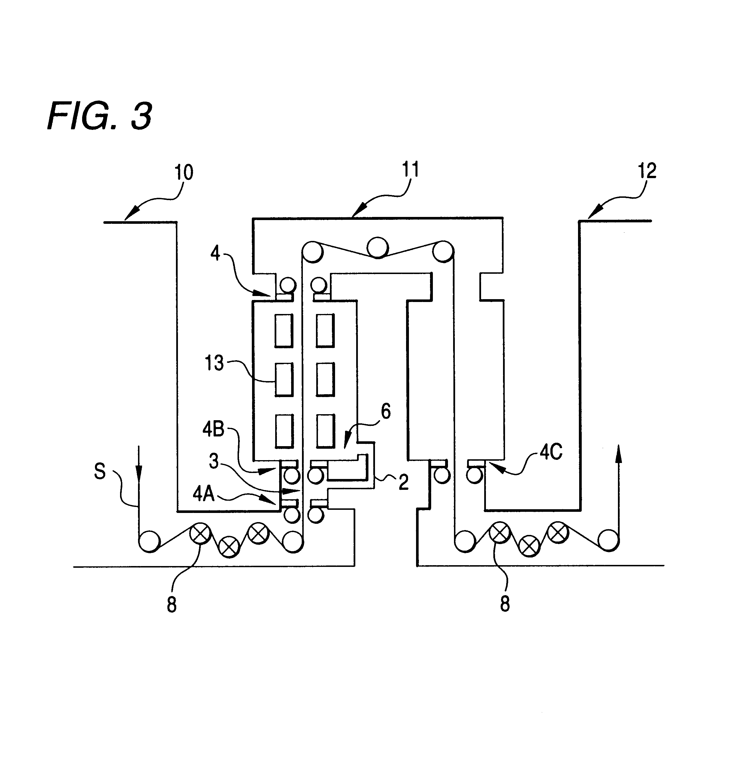
shows an example assuming a state not satisfying the conditions of the sixth invention (with no bridle rolls) in the fifth invention (same facilities as in Example 3 shown in FIG. 1), and making the tension in the rapid cooling zone equal with the tension in the heating zone which is lower than the range of the formula corresponding to any of the formulae (1) to (3) (not satisfying the conditions of the second invention).

The amount of an atmospheric gas at high hydrogen concentration (hydrogen concentration: about 30%) used in the rapid cooling zone and the frequency of occurrence of nitridation in steel strips were investigated for Example 1, Example 2, Example 3 and Example 4 described above. Further, results of the investigation (comparative examples) when operating an existent continuous heat treatment furnace while satisfying the formula corresponding to any of the formulae (1) to (3) for the tension in the furnace as shown in FIG. 4 are determined as a comparative example. FIG...


PUM

PropertyMeasurementUnit
widthaaaaaaaaaa
thicknessaaaaaaaaaa
thicknessaaaaaaaaaa

Abstract

A continuous heat treatment furnace having one of a plurality of furnace zones except for first and last zones as a rapid cooling zone 11 for rapidly cooling a material by blowing an atmospheric gas, which comprises a roll-sealed chamber 3 partitioned at the inlet by first and second roll sealing devices 4A and 4B from the upstream and a third roll sealing device 4C at the outlet as sealing means for atmospheric gas, and in which the inlet of the first roll sealing device and the outlet of the third roll sealing device are connected, and / or the roll-sealed chamber and an uppermost stream portion 6 in the rapid cooling zone are connected, and in which the hydrogen concentration in the furnace is controlled to 10% or higher in the rapid cooling zone and is controlled to 10% or lower in the furnace zone at the inlet of the rapid cooling zone. A continuous heat treatment furnace capable of simply preventing mixing of atmospheric gases in the rapid cooling zone and the atmospheric gas in the zone (heating zone, cooling zone or the like) adjacent with the rapid cooling zone of a gas jet cooling system, and a method of controlling the atmospheric gas in the furnace capable of preventing nitridation are provided.

Description

The present invention concerns a continuous heat treatment furnace and, more specifically, it relates to a continuous heat treatment furnace to be us ed for continuous heat treatment of metal strips such as strip-like materials, for example, of steel and aluminum and an operation method therefor.BACKGROUND OF THE TECHNIQUESIn the present invention, "%" for hydrogen concentration means "% by volume" here and hereinafter.The continuous heat treatment furnace is, basically, a facility for applying heat treatment of a predetermined heat pattern while continuously passing strip-like materials such as steel strips, which is constituted by successively disposing furnace zones each having a processing performance of heating / soaking / cooling (slow cooling and rapid cooling) in the order of treatment.For example, a continuous heat treatment furnace for a cold-rolled steel strips comprises, as shown in FIG. 4, a heating zone 10 for heating a steel strip S to a predetermined temperature, or furt...

Claims


Application Information

Patent Timeline
Patent Type & Authority Patents(United States)
IPC IPC(8): C21D9/573C21D9/56C21D1/613C21D1/02C21D1/56
CPCC21D9/561C21D9/565C21D9/573C21D1/02C21D1/613C21D9/563C21D1/76
Inventor UENO, NAOTOIIDA, SACHIHIROSAMEJIMA, ICHIRO
Owner JFEENG CORP
Why Eureka
Try Eureka