Apparatus for braking a set of aircraft wheels

a technology for aircraft wheels and brakes, applied in the direction of aircraft braking arrangements, braking systems, braking components, etc., can solve the problems of operating pressure recovery, difficulty in using such servo-valves, operating pressure reduction, etc., and achieve accurate operation pressure and better performance.

Inactive Publication Date: 2001-02-27
SAFRAN LANDING SYSTEMS
View PDF25 Cites 30 Cited by
  • Summary
  • Abstract
  • Description
  • Claims
  • Application Information

AI Technical Summary

Benefits of technology

The invention seeks specifically to solve this problem and to design brake apparatus that provides better performance, while being less sensitive to the phenomena of temperature and

Problems solved by technology

Such hydraulic leakage is always required in that kind of design, and the magnitude thereof makes it difficult to use such servo-valves when the hydraulic source is constituted by a hydraulic accumulator, as may be the case for an emergency circuit.
The volume of fluid consumed by the permanent leakage of such servo-valves is no longer available for powering the brakes, thereby considerably diminishing the duration and number of times the brakes can be applied before the accumulator has been emptied.
The operating pressure recovered at the outlet from a servo-valve, which pressure is a function of the magnitude of the reference c

Method used


Image

  • Apparatus for braking a set of aircraft wheels
  • Apparatus for braking a set of aircraft wheels
  • Apparatus for braking a set of aircraft wheels

Examples


Embodiment Construction

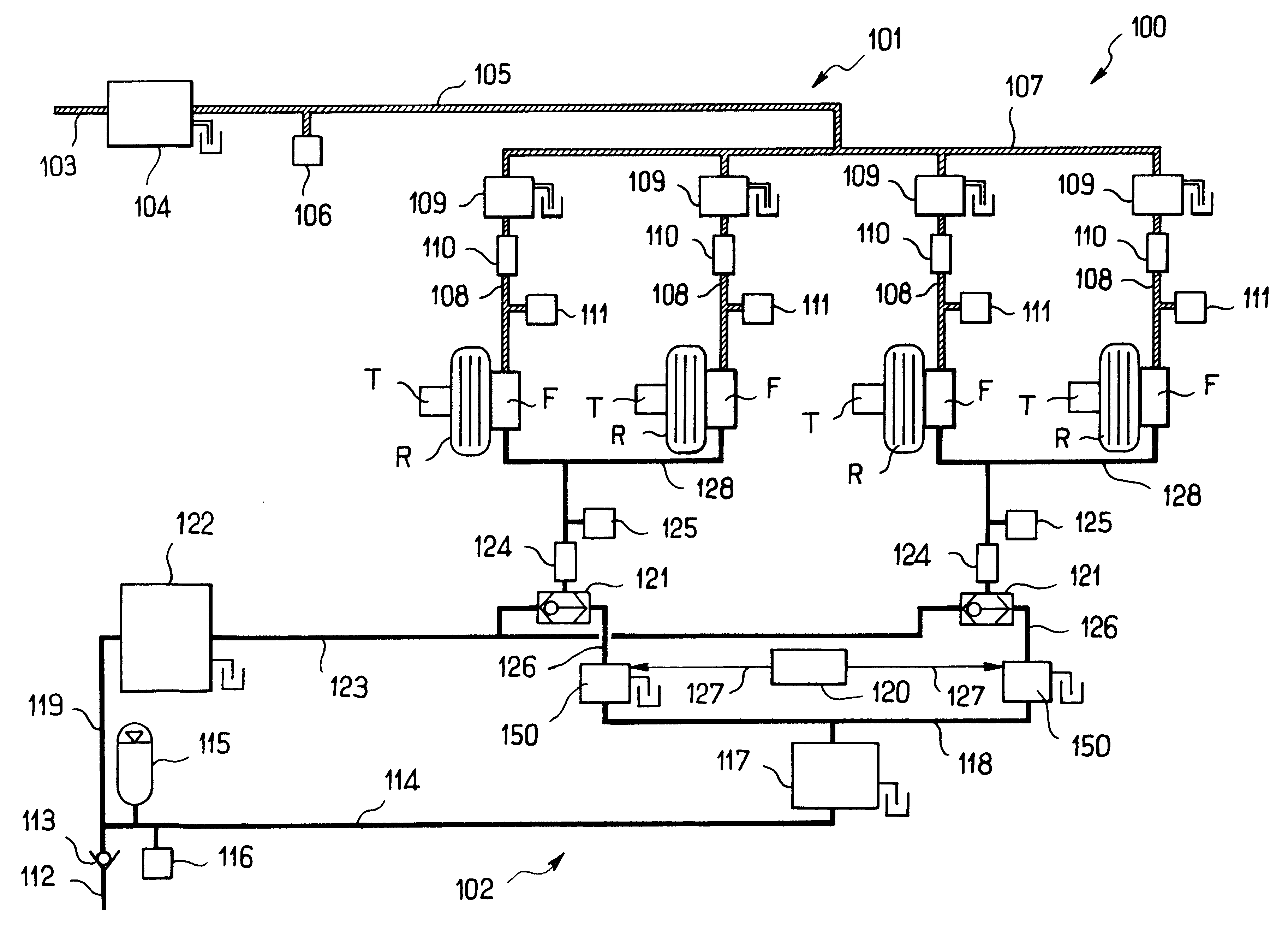
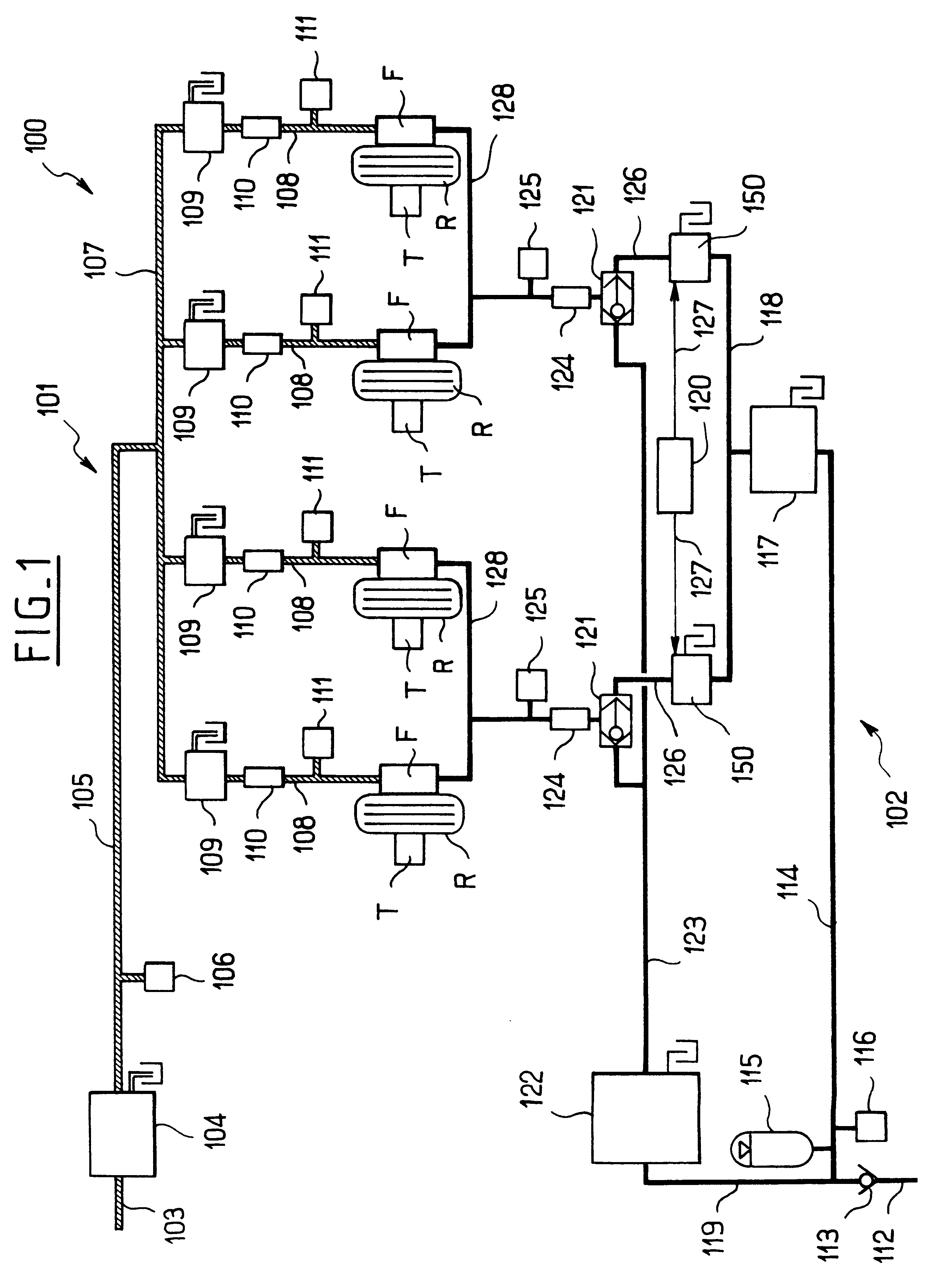
FIG. 1 shows brake apparatus for a set of aircraft wheels, and by way of example there is shown a set comprising two pairs of wheels R, one pair being to the left and the other to the right of the aircraft. The brake of each wheel is marked F and is actuated using brake pedals that are not shown herein. It will be observed that in this case, each wheel is fitted with a tachometer T, each of which delivers information relating to the speed of the corresponding wheel to electronic control members.

The brake apparatus given overall reference 100 has two sources of pressure, each feeding a hydraulic circuit. Thus, there is a "normal" hydraulic circuit 101 and a "emergency" hydraulic circuit 102 for use in the event of a breakdown.

Specifically, the normal circuit 101 is organized in conventional manner, in particular concerning its brake servo-valves referenced 109, each associated with a respective wheel brake. The various components of this hydraulic circuit 101 are therefore outlined b...


PUM


Abstract

The invention relates to apparatus for braking a set of aircraft wheels, the apparatus comprising a normal hydraulic circuit and an emergency hydraulic circuit, both circuits leading to each of the various brakes via associated brake valves. According to the invention, the brake valves of the normal circuit and/or of the emergency circuit are constituted by direct drive valves that are electrically controlled by an associated electronic control unit.

Description

The present invention relates to controlled braking of a set of aircraft wheels, and more particularly it relates to apparatus for braking a set of wheels in which the wheels are generally distributed in two groups organized symmetrically on either side of a longitudinal midplane of the aircraft, of the type in which each wheel is fitted with a brake actuated by means of brake pedals.There already exist numerous brake apparatuses fitted with a first hydraulic circuit powered by an associated hydraulic source and used for braking under normal conditions, and with an emergency hydraulic circuit powered by a different source of hydraulic pressure and used only in the event of a breakdown.Traditionally, each of the two hydraulic circuits (normal and emergency) is connected to each of the various brakes via a brake valve which is a servo-valve that is electrically controlled by a cockpit unit which measures information corresponding to brake pedal depression, and in general also to the s...

Claims


Application Information

Patent Timeline
IPC IPC(8): B64C25/42B64C25/00B60T13/68B60T17/18B64C25/44
CPCB60T8/00B60T13/686B60T17/18B64C25/42
Inventor YBERT, FRANCK
Owner SAFRAN LANDING SYSTEMS
Why Eureka
Try Eureka