Magnetoresistance effect film and magnetoresistance effect type head

a technology of magnetoresistance effect and film, applied in the field of magnetoresistance effect film and magnetoresistance effect type head, can solve the problems of insufficient sensitivity of materials, inapplicability of artificial lattice magnetic multilayer films, and inability to meet the requirements of strict heat run test,

Inactive Publication Date: 2001-02-27
TDK CORPARATION
View PDF11 Cites 23 Cited by
  • Summary
  • Abstract
  • Description
  • Claims
  • Application Information

AI Technical Summary

Problems solved by technology

However, conventional MR sensors which are formed of magnetic materials such as Ni.sub.80 Fe.sub.20 (Permalloy), NiCo or the like have a small resistance change ratio .DELTA.R / R which is about 1 to 3% at maximum, and thus these materials have insufficient sensitivity as the reading MR head materials for ultrahigh density recording of the order of several GBPSI (Giga Bits Per Square Inches) or more.
However, these artificial lattice magnetic multilayered films are not commercially applicable as they are because the external magnetic field at which a maximum resistance change occurs (operating magnetic field intensity), is as high as several tens of kilo-oersted.
However, for putting the spin valve to practical use, there are various problems as described hereinbelow.
However, it has been experimentally found out that a very strict heat run test can not be cleared by merely using such conventional protective layer materials in combination with the antiferromagnetic thin films proposed in the foregoing Japanese patent applications.
As a result, it is possible that sufficient outputs can not be ensured after completion as a spin valve head.
If this value becomes less than 1 nm, there is raised a disadvantage that the essential function as the protective layer can not be revealed.
On the other hand, if this value exceeds 5 nm, since the materials selected in the present invention, particularly Rh and Ru, have smaller resistivity as compared with conventional Ta or the like, there is raised a disadvantage that a shunt effect of sense current occurs to reduce the MR characteristic.
If this value exceeds 2,000 atomic ppm, there is raised a disadvantage that a large value of energy Jk of exchange coupling between the antiferromagnetic layer 50 and the ferromagnetic layer 40 can not be obtained.
Further, dispersion of the blocking temperatures Tb increases so that a thin film excellent in pinning effect can not be obtained.
If the upper limits of those impurity concentration ranges are exceeded, there is raised a disadvantage that a large value of energy Jk of exchange coupling between the antiferromagnetic layer and the ferromagnetic layer can not be obtained.
Further, dispersion of the blocking temperatures Tb increases so that a thin film excellent in pinning effect can not be obtained.
However, if it is too thick, a gap length (a shield-shield length) of the MR head is so increased that it is not suitable for the ultrahigh density magnetic recording.
On the other hand, if it exceeds 3000 Oe, the effect is not improved although a coil must be designed in large size due to an occurrence of magnetic field.
Therefore, the cost is increased and thus it is inefficient.
If n is excessively large, the resistance of the whole element is excessively low, and it is practically inconvenient.
However, in this case, the orthogonalization state may be disturbed by the unavoidable heat applied during the subsequent head fabricating process.
On the other hand, when the blocking temperature Tb is too lower than the temperature at which the induced magnetic anisotropy of the soft magnetic layer 20 is lost, the exchange coupling magnetic field Hua is deteriorated due to heat applied during operation of an MR sensor in the magnetic recording system and during the spin valve head fabricating process so that the magnetic multilayered film can not work as a spin valve film.
In general, a problem of heat-resistance frequently occurs in the magnetoresistance effect film having the foregoing magnetic multilayered film due to the thickness of each layer.

Method used


Image

  • Magnetoresistance effect film and magnetoresistance effect type head
  • Magnetoresistance effect film and magnetoresistance effect type head
  • Magnetoresistance effect film and magnetoresistance effect type head

Examples


example ii

[Example II]

From the foregoing experimental results, attention was paid to Rh having the most excellent function as the protective layer. Various samples were prepared as shown in Table 2 below, wherein protective layers were made of Rh while compositions of antiferromagnetic layers were variously changed. The samples were prepared substantially in the same manner as in Example I. Evaluation similar to that in Example I was performed with respect to the prepared samples. The results are shown in Table 2.

From the results shown in Table 2, it is seen that in case of the material of the protective layer being Rh, the excellent results can be obtained in the combination with the antiferromagnetic layers containing Mn no less than 40 at %. Among them, the highly excellent results can be obtained in the combination with the antiferromagnetic layer made of RuRhMn, RuPtMn or RuNiMn which contains Mn and Ru.

example iii

[Example III]

(Preparation of Inventive Sample III-1)

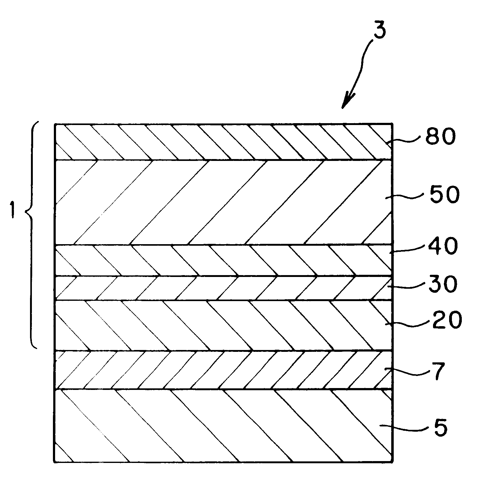
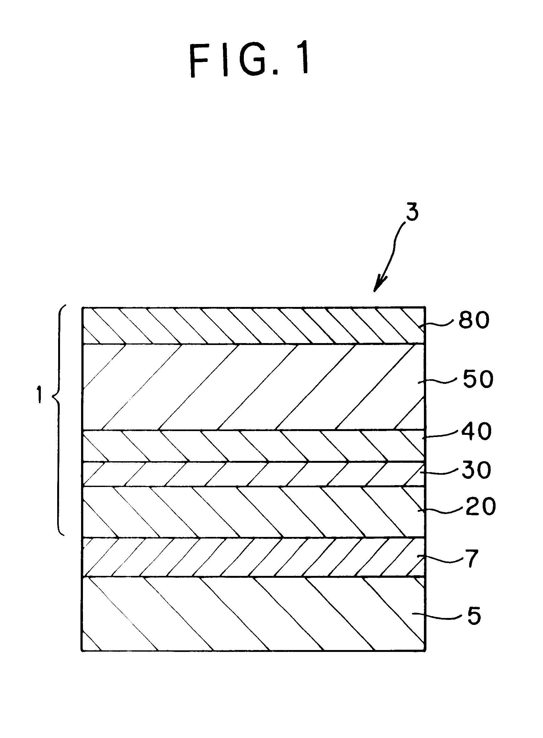
A spin valve (SV) type magnetoresistance effect film being a main part of a spin valve type magnetoresistance effect type head was prepared in the following manner. Specifically, a sample (Inventive Sample III-1) of the spin valve type magnetoresistance effect film was prepared by stacking, on a substrate 5 (AlTiC with Al.sub.2 O.sub.3), an under layer 7 (Ta; 5 nm in thickness), a soft magnetic layer 20 (NiFe; 9 nm in thickness / Co; 1 nm in thickness), a non-magnetic metal layer 30 (Cu; 2.5 nm in thickness), a ferromagnetic layer 40 (Co; 2 nm in thickness), an antiferromagnetic layer 50 (Ru.sub.4 Rh.sub.14 Mn.sub.82 ; 10 nm in thickness) and a protective layer 80 (Rh; 5 nm in thickness) in the order named.

The impurity concentration of the antiferromagnetic layer 50 was such that the oxygen concentration: 200 to 400 ppm, the carbon concentration: 80 to 200 ppm, the sulfur concentration: 80 to 300 ppm and the chlorine concentration: 5...

example iv

[Example IV]

According to the preparation of Inventive Sample I-1, various samples were prepared by variously changing the sputtering condition so as to provide the samples having different concentrations of impurities (oxygen, carbon, sulfur, chlorine) contained in the antiferromagnetic layer. Using the samples, an influence of the impurity concentration of the antiferromagnetic layer upon the exchange coupling energy Jk was examined. The results are shown in graphs of FIGS. 7 to 9. From the results, it is seen that the oxygen concentration needs to be suppressed to 1 to 2,000 ppm, the carbon concentration to 1 to 2,000 ppm, the sulfur concentration to 1 to 1,000 ppm and the chlorine concentration to 1 to 2,000 ppm for obtaining the exchange coupling energy Jk of no less than 0.1 erg / cm.sup.2.

It is confirmed that such impurity concentration suppression can be realized by sputtering a target in a vacuum film forming apparatus degassed to an ultimate pressure of no higher than 2.times...


PUM

PropertyMeasurementUnit
thicknessaaaaaaaaaa
blocking temperature Tbaaaaaaaaaa
blocking temperatures Tbaaaaaaaaaa

Abstract

In a spin valve type magnetoresistance effect film, an antiferromagnetic layer is made of MxMn100-x wherein M represents at least one selected from Ru, Rh, Re, Pt, Pd, Au, Ag, Fe, Ni, Ir and Cr, and 15<=x<=58 (unit of x: atomic %), and a protective layer formed thereon is made of at least one selected from Rh, Ru, Zr and Ti. With this arrangement, a magnetoresistance effect film highly excellent in thermal stability and small in deterioration of the MR ratio, as well as a magnetoresistance effect type head having such a magnetoresistance effect film can be obtained.

Description

1. Field of the InventionThe present invention relates to a magnetoresistance effect film for reading the magnetic field intensity of a magnetic recording medium or the like as a signal and, in particular, to a magnetoresistance effect film which is capable of reading a small magnetic field change as a greater electrical resistance change signal, and further relates to a magnetoresistance effect type head using such a magnetoresistance effect film.2. Description of the Prior ArtRecently, there has been the development for increasing the sensitivity of magnetic sensors and increasing the density in magnetic recording and, following this, magnetoresistance effect type magnetic sensors (hereinafter referred to as MR sensors) and magnetoresistance effect type magnetic heads (hereinafter referred to as MR heads) using magnetoresistance change have been actively developed. Both MR sensors and MR heads are designed to read out external magnetic field signals on the basis of the variation i...

Claims


Application Information

Patent Timeline
Patent Type & Authority Patents(United States)
IPC IPC(8): G11B5/39
CPCG11B5/3967
Inventor ARAKI, SATORUSANO, MASASHITSUCHIYA, YOSHIHIRO
Owner TDK CORPARATION
Why Eureka
Try Eureka