Switching power supply circuit

a power supply circuit and circuit technology, applied in the direction of power conversion systems, instruments, dc-dc conversion, etc., can solve the problems of increasing switching loss, complex structure of switching power supply units, and heat generation of switching elements

Inactive Publication Date: 2001-03-06
MURATA MFG CO LTD
View PDF5 Cites 44 Cited by
  • Summary
  • Abstract
  • Description
  • Claims
  • Application Information

AI Technical Summary

Benefits of technology

With this arrangement, the switching power supply circuit of the present invention has a simple structure, in which intermittent switching operations under light load can be performed without the need for intermittent / continuous switching signals. As a result, heat generation and power loss of the switching element under the light load can be reduced.
With this arrangement, in the switching power supply circuit of the present invention, even when intermittent switching operations are performed under light load, a high quality output in which output voltage ripple is small can be obtained.

Problems solved by technology

Usually, there are problems in that since the switching frequency significantly rises under light load, the switching element generates heat and switching loss increases.
In this case, since it is necessary to dispose the current detecting unit 6 and intermittent / continuous switching signal generating unit 7, there are problems in that the structure of the switching power supply unit becomes complicated, and miniaturization of the circuit is thereby hindered and cost increases.

Method used


Image

  • Switching power supply circuit
  • Switching power supply circuit
  • Switching power supply circuit

Examples


Embodiment Construction

Hereinafter, the preferred embodiments of the present invention are explained in detail with reference to the drawings.

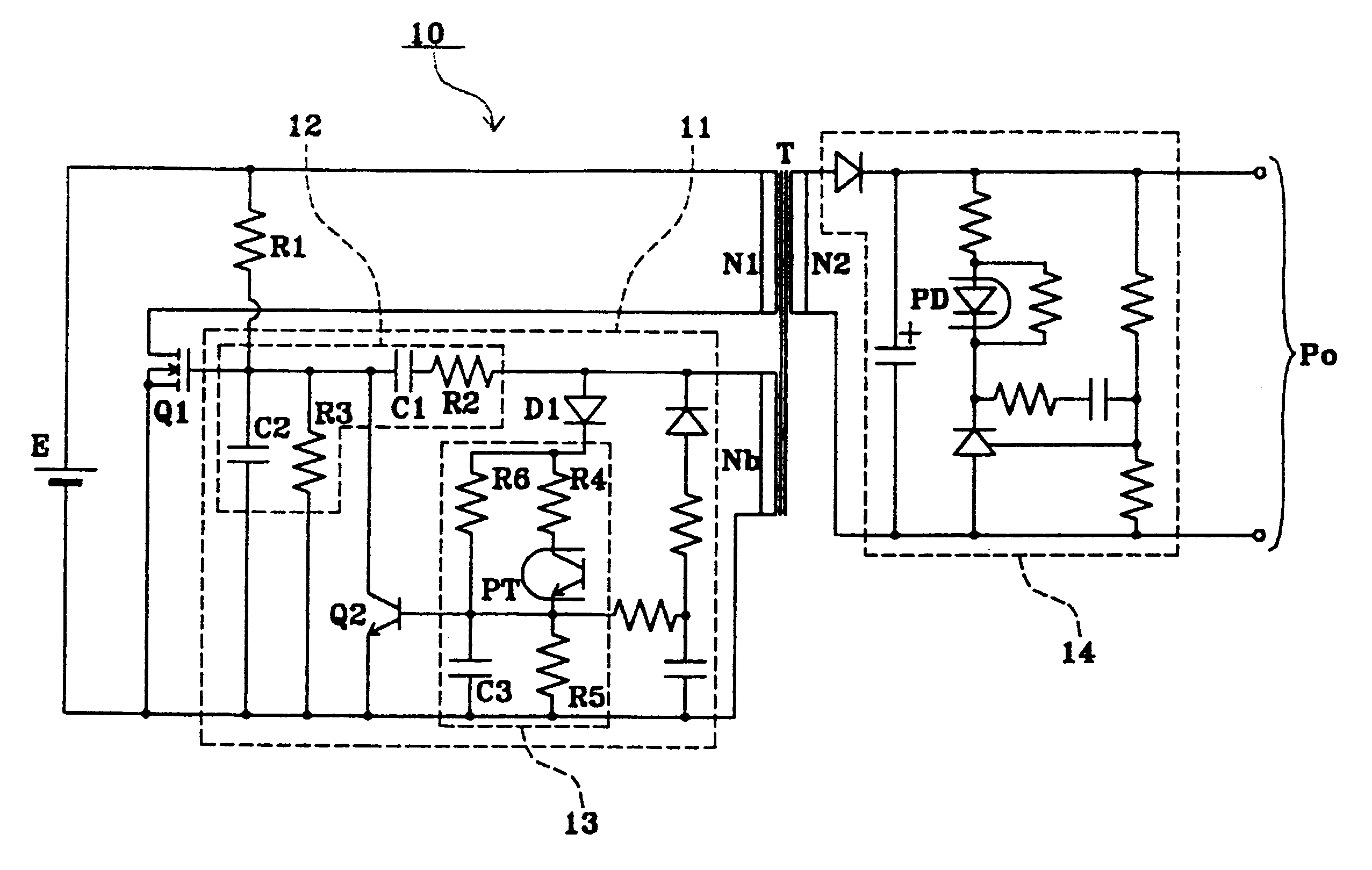
FIG. 1 shows a switching power supply circuit according to an embodiment of the present invention. In FIG. 1, the same reference numerals are given to the same parts as those shown in FIG. 3, and are given to the equivalent parts thereto. However, the explanation of the same and equivalent parts is omitted.

A switching power supply circuit 10 shown in FIG. 1 is a switching power supply circuit of the RCC (Ringing Choke Converter) system, in which an end of a first winding N1 of a transformer T is connected to the drain of an FET Q1 as a switching element, and the source of the FET Q1 is connected to the negative pole of a direct-current power supply E. In addition, the other end of the first winding N1 is connected to the positive pole of the direct-current power supply E. Furthermore, the positive pole of the direct-current power supply E is connected to the gate of...


PUM


Abstract

A switching power supply circuit includes a transformer having a primary winding, a secondary winding, and a feedback winding, a switching element connected in series to a first of the primary winding, a control circuit disposed between a control terminal of the switching element and the feedback winding, a starting circuit connected between a second end of the primary winding and the control terminal of the switching element, and a rectifying / smoothing circuit connected to the secondary winding. The control circuit includes a first delay circuit for determining the time that elapses before the switching element is turned on by a voltage generated at the feedback winding, a control element driven to prevent the switching element from turning on or forcibly turn off the switching element, and a second delay circuit for changing a delay time such that, under rated load or under heavy load, the switching element is turned off by driving the control element after the switching element is turned on by the voltage generated at the feedback winding, and, under light load, the turn-on of the switching element is blocked by driving the control element before the switching element is turned on by the voltage generated at the feedback winding.

Description

1. Field of the InventionThe present invention relates to switching power supply circuits, and more particularly, the invention relates to switching power supply circuits in which heat generation and power loss in the switching element can be reduced by performing intermittent switching operations under light load.2. Description of the Related ArtFIG. 3 shows a conventional switching power supply circuit disclosed in Japanese Unexamined Patent Application Publication No. 4-12666, which can perform intermittent switching operations under light load.In FIG. 3, a switching power supply circuit 1 has a DC power supply E, a switching unit 2, a switching control unit 3, a transformer T which includes a primary winding N1, a secondary winding N2, and a feedback winding Nb, a rectifying / smoothing circuit 4, a first photo coupler (PC) 5, a current detecting unit 6, an intermittent / continuous switching signal generating unit 7, and a second photo coupler 8. In this case, the power supply E is...

Claims


Application Information

Patent Timeline
Patent Type & Authority Patents(United States)
IPC IPC(8): H02M3/24H02M3/338H02M3/28
CPCH02M3/3381H02M3/3385
Inventor HOSOTANI, TATSUYATAKEMURA, HIROSHI
Owner MURATA MFG CO LTD
Why Eureka
Try Eureka