Miniature combination valve and pressure transducer system

Inactive Publication Date: 2001-03-13
WIDNER RONALD D
View PDF29 Cites 150 Cited by
  • Summary
  • Abstract
  • Description
  • Claims
  • Application Information

AI Technical Summary

Problems solved by technology

MEMS pressure measurement devices of the type disclosed by Schuenemann et al. are not well-suited for installation in small, confined spaces and through apertures because their packages are relatively large.
Such an arrangement would be impractical because fine wires are likely to break under the stresses to which tires an

Method used


Image

  • Miniature combination valve and pressure transducer system
  • Miniature combination valve and pressure transducer system
  • Miniature combination valve and pressure transducer system

Examples


Example

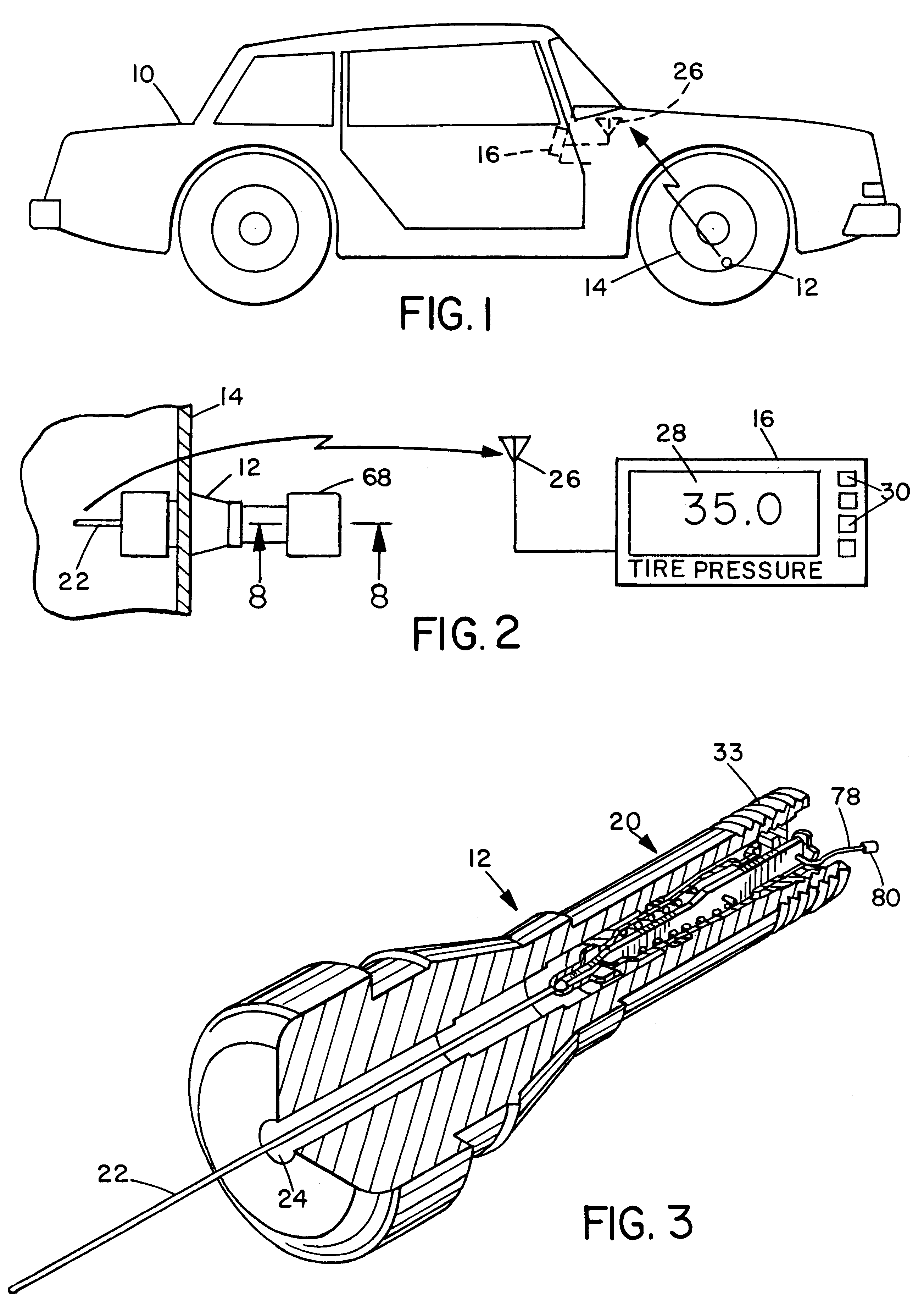
As illustrated in FIG. 1, a remote pressure-monitoring transducer valve system may be used in an automobile 10 or other vehicle or machine having inflation valves, such as a truck, bus, cart, bicycle, motorcycle or aircraft. The system includes a transducer valve 12 mounted on each of one or more rims 14 of the automobile's tires 15 and a receiver unit 16 mounted in the automobile passenger compartment. As described below in further detail, transducer valve 12 measures the air pressure within the tire 15 and transmits a value representing the measured pressure to receiver unit 16, which provides a suitable indication, such as a numerical pressure measurement or an overinflation or underinflation alarm signal, to the automobile driver or other user.

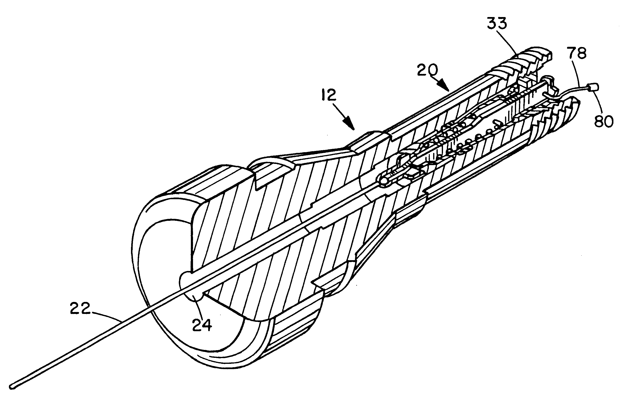
As illustrated in FIG. 2, transducer valve 12 is mounted through the rim 14 in the manner of a conventional automobile tire inflation valve. Indeed, as illustrated in FIG. 3 and described below in further detail, in the illustrated embodim...


PUM


Abstract

A valve system includes a movable microelectromechanically structured (MEMS) pressure sensor that not only senses pressure but also functions as a mechanical actuator for the valve. An alternative valve system includes a MEMS pressure sensor that extends through an aperture in a curved wall, such as a curved wall of a valve body or a valve core, at an oblique angle to allow it be securely mounted in the confined space of an automotive-type tire inflation valve. The valve system includes a transmitter integrated with the valve and a receiver located at a remote location, such as the passenger compartment of an automobile.

Description

1. Field of the InventionThe present invention relates generally to electronic pressure measurement devices and, more specifically, to a miniature valve system that includes an integral pressure transducer.2. Description of the Related ArtA pressure transducer is a device that produces an electric signal in response to a pressure of a gas or liquid. Following the general trend toward miniaturization of electronic components, pressure measurement devices have been produced that include the transducer itself plus associated electronic components needed to produce a useful output signal co-fabricated on a monolithic integrated circuit chip. Such a pressure measurement device is a type of microelectromechanical structure (MEMS). MEMS technology involves producing integrated micro devices or systems that combine electronic components formed on the semiconductor substrate and three-dimensional mechanical components fabricated in the substrate. Sensors and actuators are the primary categor...

Claims


Application Information

Patent Timeline
IPC IPC(8): B60C23/00B60C23/04B60C23/02
CPCB60C23/004B60C23/0401B60C23/0408B60C23/0433Y10T137/3662Y10T137/8326
Inventor WIDNER, RONALD D.
Owner WIDNER RONALD D
Why Eureka
Try Eureka