
High temperature refractory joining paste

a refractory and high temperature technology, applied in the direction of manufacturing tools, non-electric welding apparatus, welding apparatus, etc., can solve the problems of mechanical joint failure, broken sintering furniture, repair or discarded,

Inactive Publication Date: 2001-03-13
IBM CORP
View PDF22 Cites 34 Cited by
  • Summary
  • Abstract
  • Description
  • Claims
  • Application Information

AI Technical Summary

Benefits of technology

is to provide a novel eutectic system for transient liquid phase bonding of refractory metal structures wherein the resulting joint does not contain elements which would substantially affect the bonding process or the quality of the joint.
Preferably, during step (e) the material having a lower melting point than the refractory material forms a localized liquid region with the refractory material at the surfaces in need of joining wherein the material having a lower melting point than the refractory material diffuses into the refractory metal components and into the refractory material of the paste. Preferably, during step (f) the material having a lower melting point than the refractory material diffuses into the refractory metal components forming a solid joint as the localized liquid region decreases its concentration of the material having a lower melting point than the refractory material thereby becoming more refractory.

Problems solved by technology

Occasionally, the sintering furniture breaks and must be repaired or discarded.
However, due to the expansion and contraction of the pieces during thermal cycling of the furnace, the mechanical joint would fail.

Method used


Image

  • High temperature refractory joining paste
  • High temperature refractory joining paste

Examples


Embodiment Construction

)

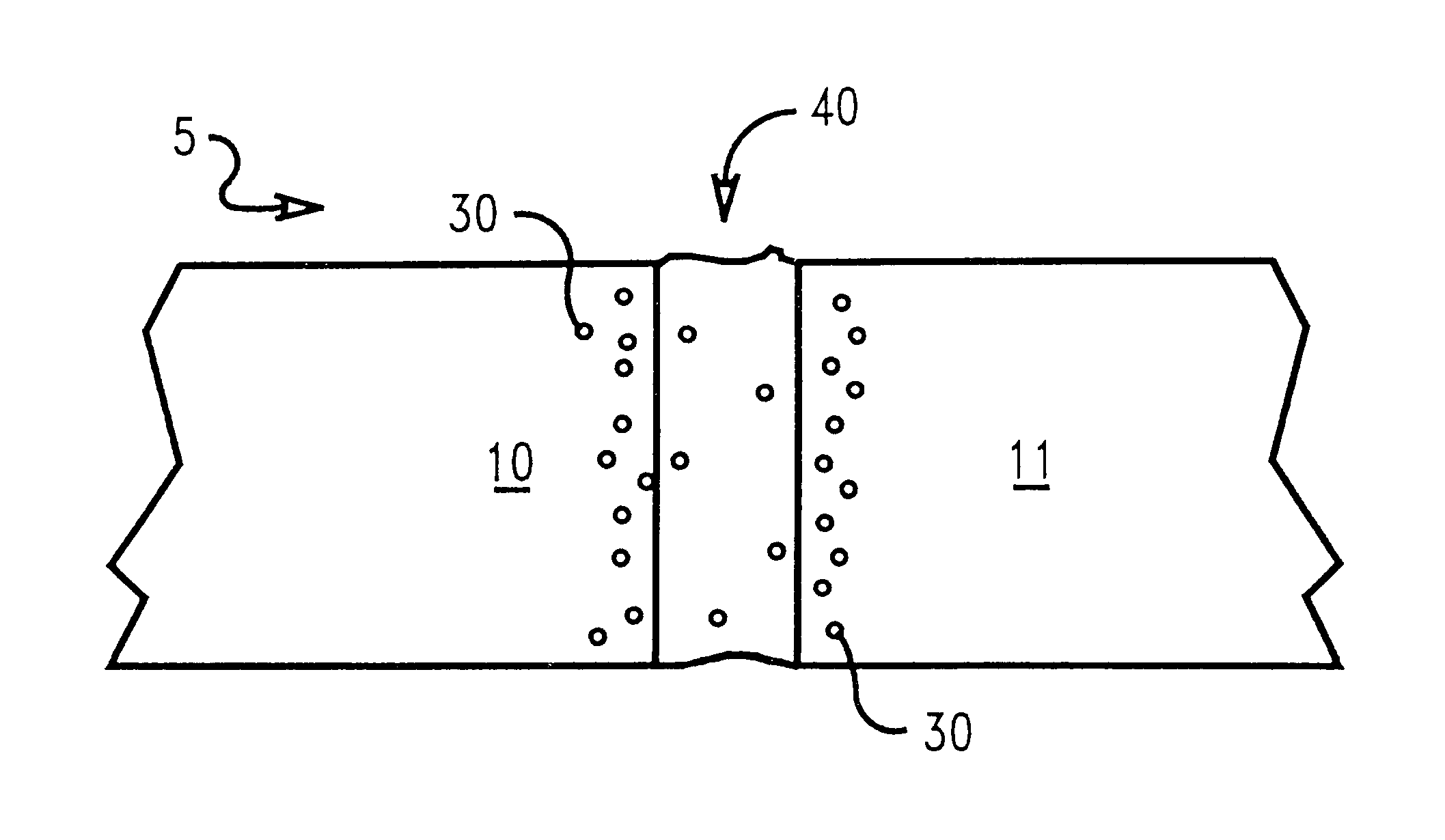
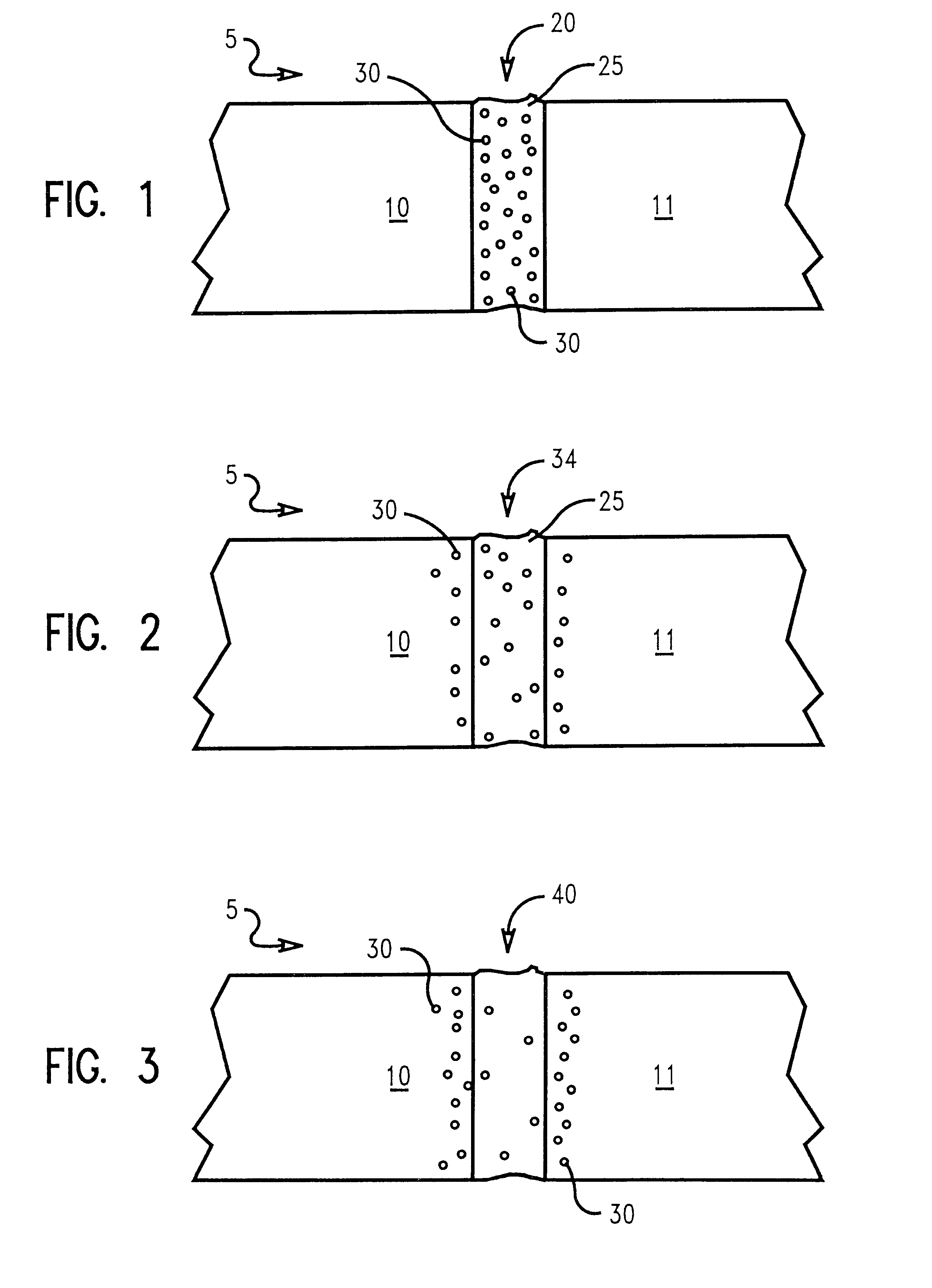
In describing the preferred embodiment of the present invention, reference will be made herein to FIGS. 1-3 of the drawings in which like numerals refer to like features of the invention. Features of the invention are not necessarily shown to scale in the drawings.

The present invention relates to the bonding of refractory metal structures such as sintering furniture or hardware by use of a refractory metal paste having metallic constituents wherein the resultant joint maintains the structural integrity of the refractory metal structures at the high operating temperatures of the structures. Preferably, the refractory metal paste comprises a first component substantially similar to the composition of the refractory metal structure, and a second component having a lower melting temperature than the first component comprising a metallic constituent selected from the group consisting of iron, nickel and cobalt. The second component acts as a melting point depressant to temporarily lower...


PUM

PropertyMeasurementUnit
Fractionaaaaaaaaaa
Temperatureaaaaaaaaaa
Thicknessaaaaaaaaaa

Abstract

A method of and novel composition for transient liquid phase bonding of refractory metal structures is described herein. Preferably, the composition comprises a first component substantially similar to the composition of the refractory metal structure, and a second component having a lower melting temperature than the first component comprising a metallic constituent selected from the group consisting of iron, nickel and cobalt. The second component acts as a melting point depressant to temporarily lower the melting point of the first component so that the join can be accomplished without melting the structure itself. Upon applying the composition to the surfaces of refractory metal structures in need of joining, the assembly is heated to a eutectic point defined as the lowest melting point of the composition. A localized liquid region is formed at the interface of the two structures which solidifies when the second component diffuses into the structures such that the region becomes increasingly refractory thereby solidifying into a substantially refractory joint.

Description

1. Field of the InventionThis invention relates to a method of and novel composition for use in joining refractory metal structures, and, more particularly, to the transient liquid phase bonding of such refractory metal structures.2. Description of Related ArtRefractory metal structures may be employed as support structures in high temperature sintering furnaces known as sintering furniture or hardware. Oftentimes, the sintering furniture is made from molybdenum to withstand operating temperatures of up to 1700.degree. C. Occasionally, the sintering furniture breaks and must be repaired or discarded. Attempts at cost containment have led to methods of repairing the sintering furniture. Most preferably, repairing the sintering furniture achieves a defect free bond joint having a strength comparable to that of the sintering furniture itself.Typically, repairs have been made by mechanically joining the broken pieces together. The mechanical joining process may comprise forming nubs on ...

Claims


Application Information

Patent Timeline
IPC IPC(8): B23K20/02B23K20/16B23K35/32B23K35/02B23K35/24
CPCB23K20/023B23K20/16B23K35/025B23K35/32
Inventor COHN, MICHAEL A.DEGEORGE, JOSEPH P.VALLABHANENI, RAO V.
Owner IBM CORP
Learn More