Drive unit with coolant flow through a space separating an inverter from a casing housing an electric motor

Inactive Publication Date: 2001-03-13
AISIN AW CO LTD
View PDF7 Cites 108 Cited by
  • Summary
  • Abstract
  • Description
  • Claims
  • Application Information

AI Technical Summary

Problems solved by technology

However, when the controller is integrated with the electric motor, not only does the temperature of the controller rise due to the heat generated by its own elements, but it is also affected by the heat from the electric motor and therefore requires cooling.
However, accor

Method used


Image

  • Drive unit with coolant flow through a space separating an inverter from a casing housing an electric motor
  • Drive unit with coolant flow through a space separating an inverter from a casing housing an electric motor
  • Drive unit with coolant flow through a space separating an inverter from a casing housing an electric motor

Examples


first embodiment

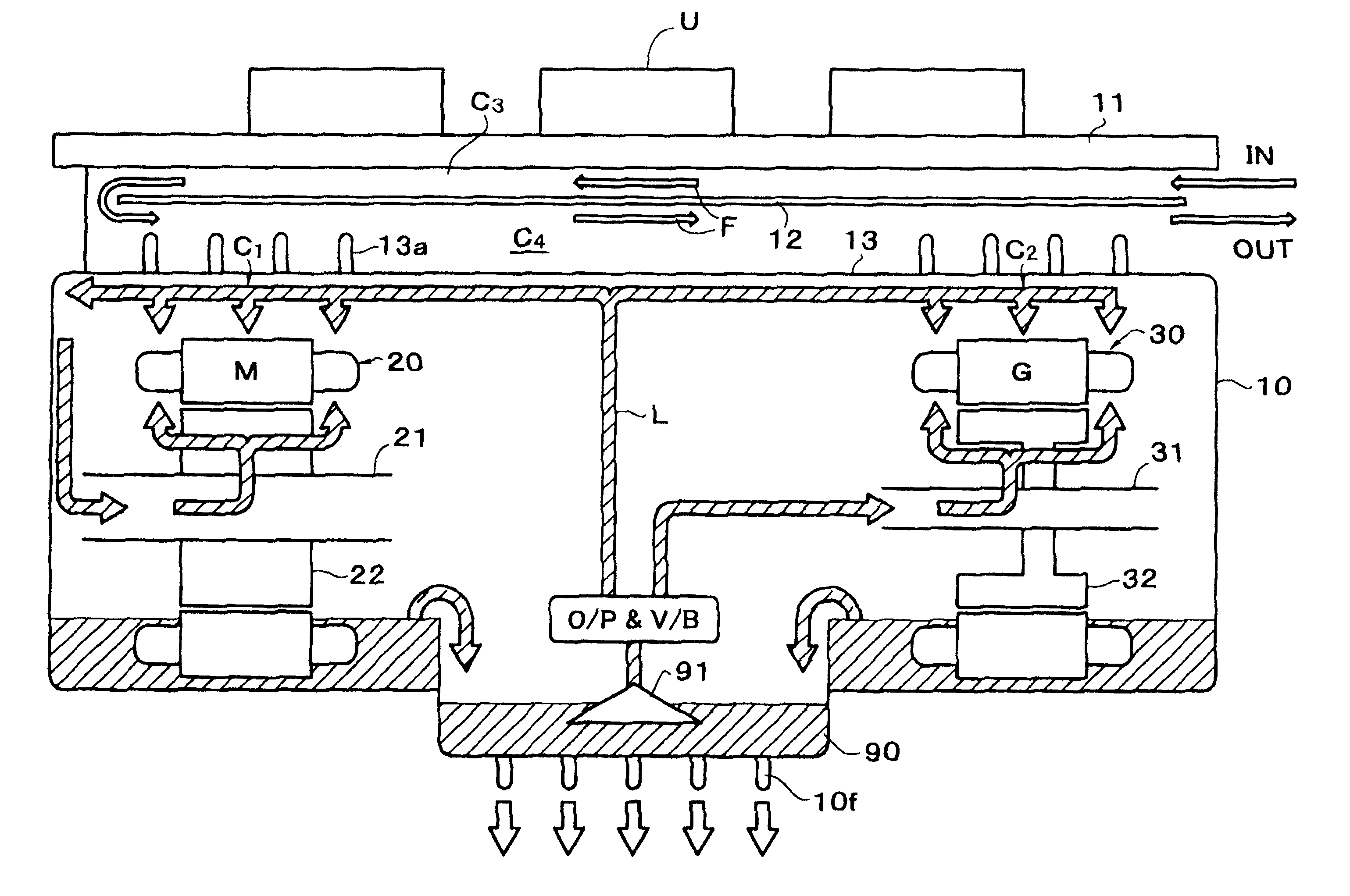
Thus, described above, because the flow passages for coolant between the motor M and the inverter U are stacked as two layers, one on the motor M side and the other on the inverter U side, the cooling water which flows therethrough acts as two heat insulating layers, and it becomes possible to block the heat on the motor M side, which becomes hotter than the inverter U side, by absorbing it in two steps with the cooling water in the flow passage so that it becomes difficult for the heat from the motor to be transferred to the inverter U. As a result, it is possible to prevent the temperature of the inverter U from rising due to the integration of the motor M and the inverter U. Furthermore, as the isolating means 12 (a heat insulator) is disposed on the inverter panel 11, it resists heat transfer to the cooling water which flows through the first chamber C.sub.3 on the inverter U side.

Furthermore, because the sequence is such that the cooling water first cools the power module form...

second embodiment

With this second embodiment, because the cooling water flows through the first chamber C.sub.3 and the second chamber C.sub.4 are independent, the heat of the motor M is prevented from being transferred to the inverter U through the cooling water. Moreover, since it is possible to run the cooling water at a lower temperature to the second chamber C.sub.4 side facing the heat transfer wall 13 portion, the cooling efficiency of the motor M and the generator G can be further improved.

Next, FIG. 11 shows a third embodiment wherein the flow of cooling water the first and second chambers C.sub.3 and C.sub.4 are the reverse of the flow pattern of the first embodiment (FIG. 5). In this embodiment, the cooling water as the second coolant first flows through the second chamber C.sub.4 to cool the oil through the heat transfer wall portion 13. Then it flows through the first chamber C.sub.3 to cool the power module of the inverter U.

third embodiment

In this third embodiment the cooling water (second coolant) does not directly cool the motor M and the generator G but, rather, cools the oil which, in turn, circulates around the motor and generator, and cools them. Therefore, the heat from the motor M and the generator G is reduced by heat exchange with the cooling water through the oil, as opposed to direct heat transfer, whereby an advantage is gained in that it is possible to prevent the temperature of the cooling water from rising above the maximum which can be tolerated by the inverter U.

FIG. 12 shows a fourth embodiment wherein the structures of the members defining the water flow passage have been modified relative to corresponding structures of the first and second embodiments. In this fourth embodiment, an independent surrounding wall member 14 is interposed between the drive unit case 10 and the inverter panel wall 11, and further, an independent isolating means 12 is interposed between the inverter panel 11 and the case...


PUM


Abstract

A drive unit which uses an electric motor as a power source and has an integrated inverter, with a cooling circuit for the electric motor and the inverter. The drive unit includes a drive unit case, the electric motor housed within the case, and the inverter fixed to the case. A coolant flow passage is provided between the drive unit case and the inverter. The inverter is fixed to the drive unit case through a panel wall, and a partition divides the coolant flow passage into chambers which are coextensive in parallel. As a result, the coolant which flows through the coolant flow passage acts as a two-stage heat shield, barring the heat generated by the electric motor from being transmitted to the inverter.

Description

1. Technical Field of the InventionThe present invention relates to a drive unit in which an electric motor is used as a power source, and more particularly, to a cooling system in a drive unit for an electric vehicle or a hybrid drive unit.2. Related ArtWhen an electric motor is used as a drive source for a vehicle, the load exerted on the electric motor varies significantly according to the running conditions. Accordingly, in order to manage the heat generated under a heavy load, cooling is necessary. Also, an electric motor requires a controller, e.g., an inverter in the case of an alternating current electric motor. Since a controller such as an inverter is connected to the electric motor with a power cable, it can be separated from the electric motor and mounted in an appropriate position. However, for mounting convenience in a vehicle, arrangements have also been used in which the inverter is integrated with the electric motor.However, when the controller is integrated with th...

Claims


Application Information

Patent Timeline
IPC IPC(8): B60K6/04B60K6/00H02K7/116H02K9/19H02K11/04H02K16/00B60K1/00B60K1/02B60K6/20B60K6/22B60K6/26B60K6/405B60K6/44B60W10/26
CPCB60K6/26B60K6/405B60K6/445B60W10/26H02K7/116H02K9/19H02K11/0073H02K16/00B60L1/003B60L1/02B60L3/003B60L3/0061B60L11/123B60L11/14B60L15/007B60L15/20B60K1/00B60L2240/525B60K2001/003F01P2050/24F01P2050/30Y10S903/903Y10S903/906Y10S903/952Y10S903/904Y02T10/6239B60L2210/40B60L2240/36B60L2240/421B60L2240/423B60L2240/425B60K1/02H02K11/33B60L50/61B60L50/16Y02T10/62Y02T10/64Y02T10/72Y02T10/7072Y02T10/70
Inventor HARA, TAKESHIHOTTA, YUTAKATAKENAKA, MASAYUKIAGATA, HIROMICHIYAMAGUCHI, KOZOKIDO, TAKAHIROKUTSUNA, NARUHIKO
Owner AISIN AW CO LTD
Why Eureka
Try Eureka