
Quick response perimeter intrusion detection sensor

a sensor and perimeter intrusion technology, applied in the field of short-range radar sensors, can solve the problems limited range of photoelectric systems, and high false alarms of beam breaker devices, and achieve the effects of low false alarm rate, increased range against airborne targets, and high reliability

Inactive Publication Date: 2001-03-27
ANRO ENG
View PDF10 Cites 69 Cited by
  • Summary
  • Abstract
  • Description
  • Claims
  • Application Information

AI Technical Summary

Benefits of technology

It is still another object of the invention to have increased range against airborne targets.
It is yet another object that the cost of the invention be minimal.

Problems solved by technology

The microwave beam breaker is subject to high levels of false alarms especially under varying weather conditions; the photoelectric system is, generally, limited in range.
Their range, however, is limited to less than 100 feet.
Some sonic sensors have ranges beyond 100 feet, but cannot resolve multiple targets.
Optical cameras, coupled with infrared night-vision and motion-sensing capabilities, can only view narrow azimuths, and are currently very expensive to implement.
However they are subject to false detections because of clutter.
The limits on detecting crawling targets depend on the height and frequency of the radar sensor because of likely signal cancellation due to ground bounce.
Besides being a very low radar cross-section target, the radar response from a crawler close to the ground is especially sensitive to ground bounce cancellation.
And since the speed of light travels one foot in 1 nanosecond, this translates to a time delay difference of but 133 picoseconds.
A prime problem is to somehow accommodate, automatically, the varying amounts of ground or sea clutter present within the radar field of view, and still achieve detection while maintaining a high probability of detection and a low probability of false alarm.
The waveform is very complicated, as expected, but the peak value within the range gate changes sufficiently over a short time to positively identify that an intruder is present within the range gate.
The result is a received signal approaching white noise in viewing, and the transmission is difficult to detect other than by a specially equipped receiver.

Method used


Image

  • Quick response perimeter intrusion detection sensor
  • Quick response perimeter intrusion detection sensor
  • Quick response perimeter intrusion detection sensor

Examples


Embodiment Construction

A successful perimeter detection sensor includes the ability to:

1. Locate the presence of intruders with a high probability of detection and a low probability of false alarm.

2. Detect intruders in moderate clutter environment such as bushes, trees, high grass, rocks, etc., including windy conditions.

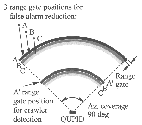
3. Detect human targets such as walkers, crawlers, and runners in addition to vehicles at ranges varying from 300 feet for walkers, to at least 150 feet for crawlers

4. Have a coverage angle of 90 degrees or greater.

5. Be quick and easy to install by a single person. Its size should be less than 0.5 cubic feet.

6. Have a low primary power drain so that it may operate over many hours in remote locations from a given battery source.

7. Be covert so that electronic instruments or visual observation cannot easily detect its presence.

8. Be capable of operation in all weather conditions and over wide temperature extremes.

9. Use a technology that is low cost to produce in quantity.

Referring to FIG...


PUM


Abstract

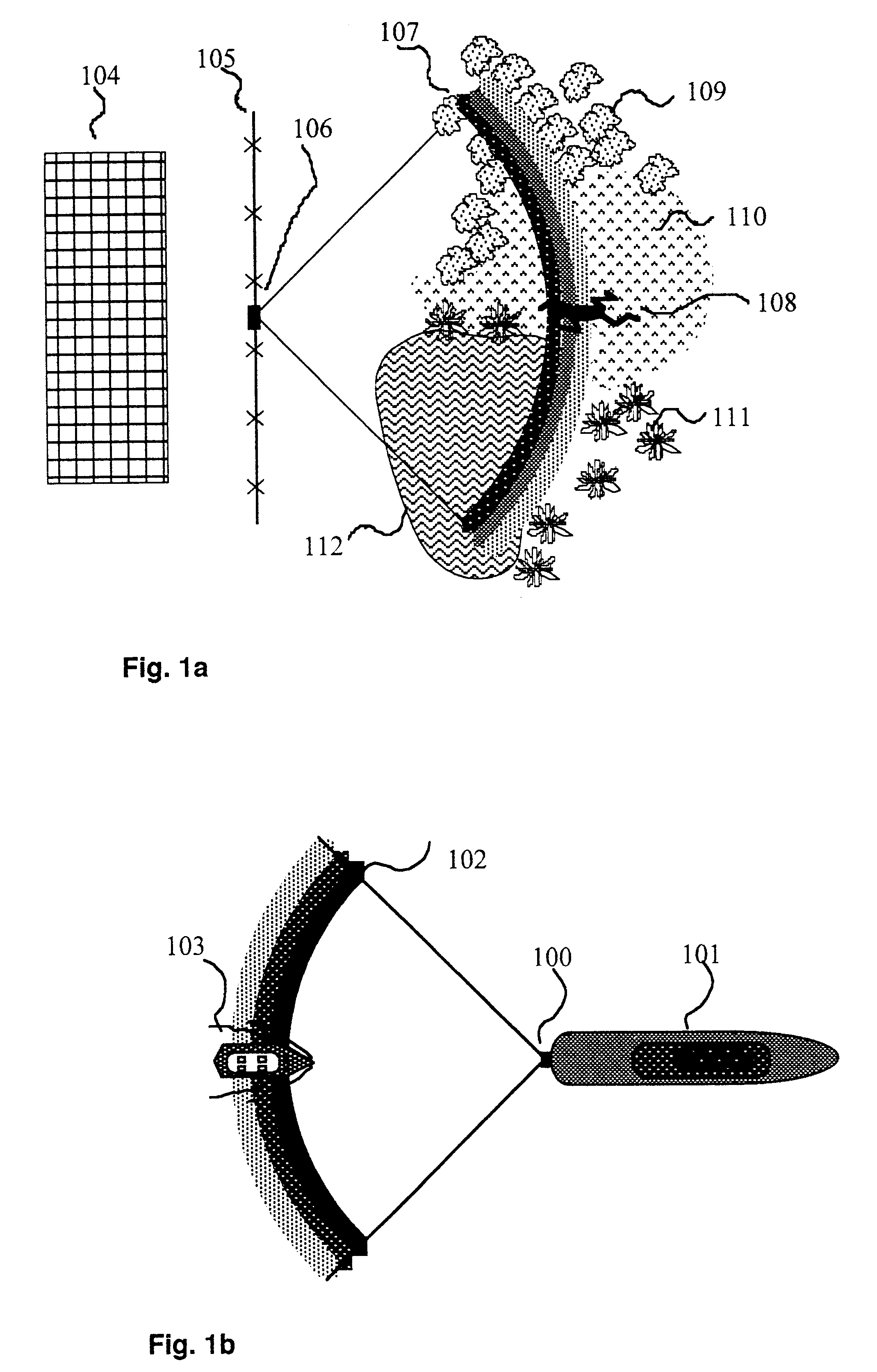
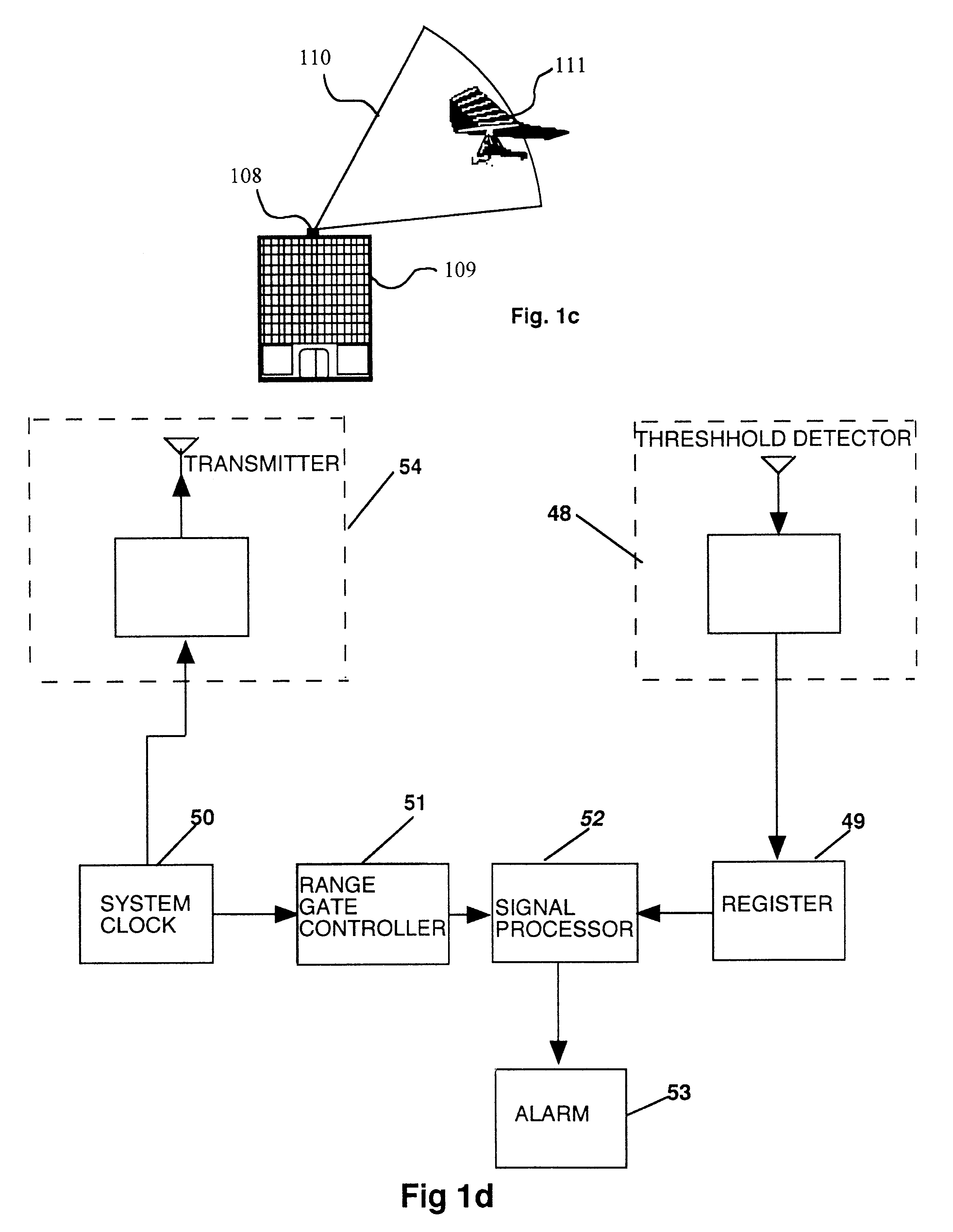
An Ultra Wideband (UWB) short-range radar system is used for the detection of targets in clutter. Examples of targets on the ground include human walkers, crawlers and runners, and vehicles. The UWB sensor can also be used to detect small approaching boats in different levels of sea clutter or airborne targets like hang gliders. One of the primary differences between this device and other UWB radar sensors is the manner in which the bias on the threshold detector is set as well as the logic circuitry used to find targets in clutter while maintaining a low false alarm rate. The processing is designed to detect targets in varying degrees of clutter automatically. There may be no front panel controls other than an ON-OFF switch. The system is lightweight, low-cost, and can be easily installed in minutes.

Description

REFERENCESU.S. Patents Documentsa. U.S. Pat. No. 3,728,632 April 1973 Gerald F. Ross Transmission and Reception System for Generating and Receiving Base-band Pulse Signals Without Distortionb. U.S. Pat. No. 3,735,395 May 1973 Gerald F. Ross Base-band Short Range Pre-collision Sensor for activation of Vehicle Safety Apparatusc. U.S. Pat. No. 3,739,392 June 1973 Gerald F. Ross, Kenneth W. Robbins Base-band Radiation and Reception Systemd. U.S. Pat. No. 3,772,697 November 1973 Gerald F. Ross Base-band Pulse Object Sensor Systeme. U.S. Pat. No. 3,755,696 August 1973 A. M. Nicolson, Robert Brophy Detector Having a Constant False Alarm Rate and Method for Providing Samef. U.S. Pat. No. 3,858,205 December 1974 Gerald F. Ross Baseband Precollision Sensor with Time-domain Gating for Preventing False Alarmsg. U.S. Pat. No. 3,858,204 December 1974 Kenneth W. Robbins Closed Loop Gain Control Tunnel-Diode Base-band Object Detectorh. U.S. Pat. No. 3,983,422 September 1976 A. M. Nicolson, Richard ...

Claims


Application Information

Patent Timeline
IPC IPC(8): G01S13/00G01S13/02G01S7/292G01S13/18G01S13/88
CPCG01S7/2922G01S13/0209G01S13/18G01S13/886
Inventor ROSS, GERALD F.
Owner ANRO ENG
Learn More