

Harmonic component measuring method for power system
a technology of harmonic components and power systems, applied in the direction of electric devices, instruments, transportation and packaging, etc., can solve the problems of inability to accurately determine the equal circuit based on the admittance (impedance) of the harmonic upstream and downstream from the connection point of the filter in the power system, and the equal circuit to the harmonic cannot be found separately with accuracy, so as to prevent a frequency analysis error
- Summary
- Abstract
- Description
- Claims
- Application Information
AI Technical Summary
Benefits of technology
Problems solved by technology
Method used
Image

Examples
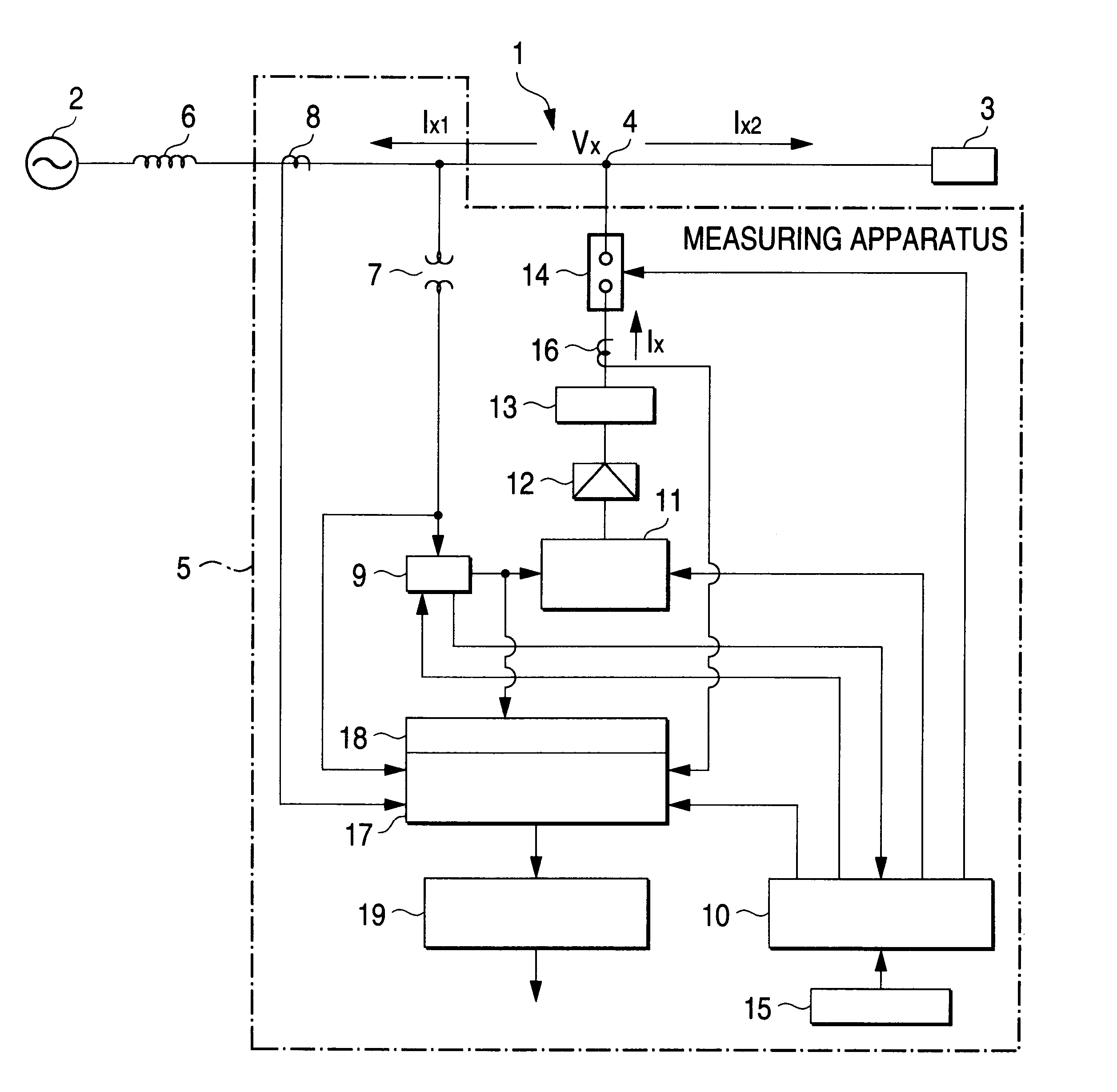
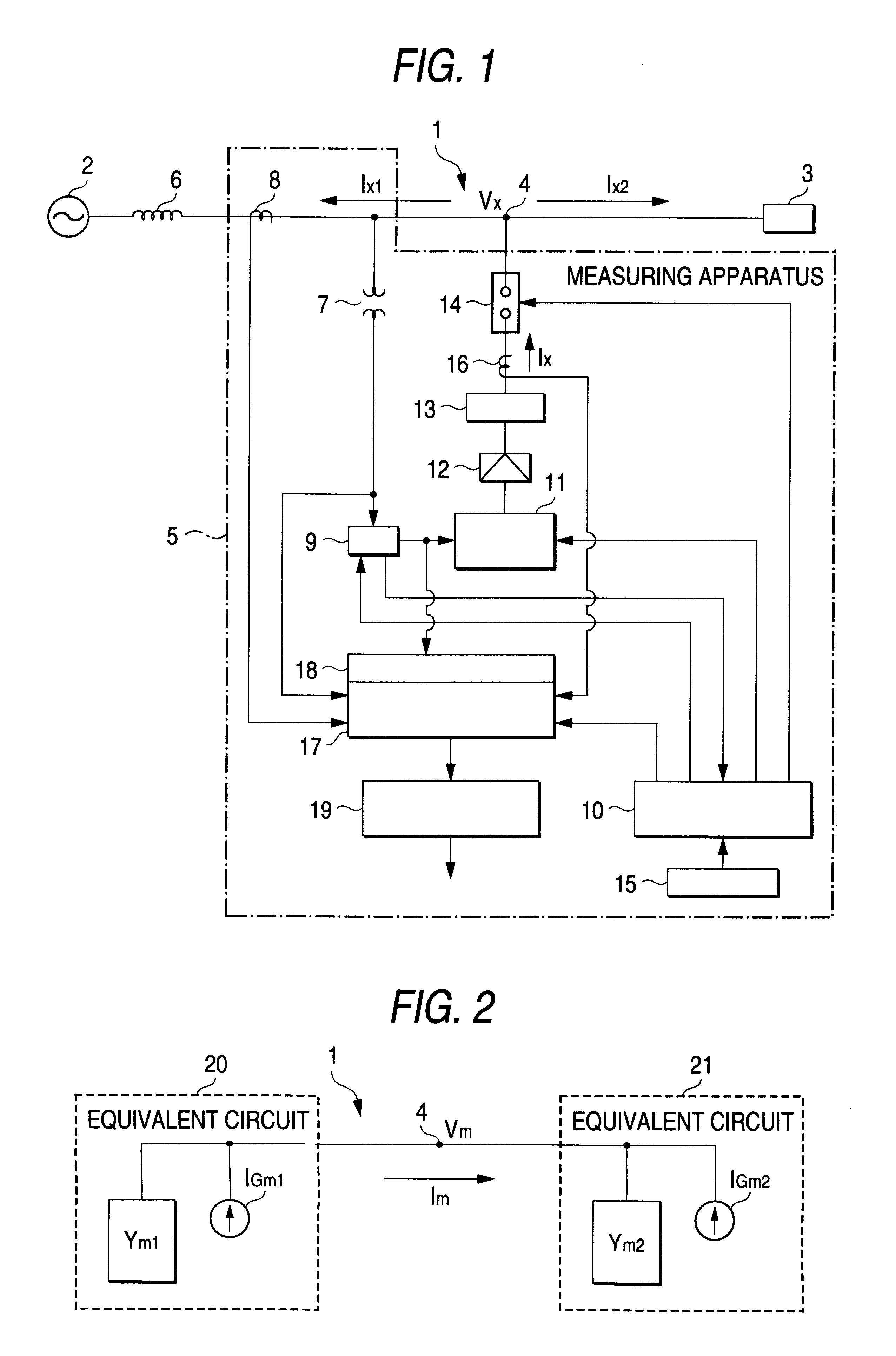
first embodiment
(Another Form of First Embodiment)
Next, a form will be discussed wherein a harmonic equivalent circuit in the power system 1 is a series circuit of an impedance and a voltage source and the impedance for the measurement harmonic on the upstream or downstream side or an equivalent circuit of the impedance and voltage source is found.
In this form, if a voltage Vx, of an intermediate-degree harmonic fx found from Expression 1, is applied to the harmonic inject point 4 in n cycles of the fundamental wave and is measured, an expression provided by changing the admittance Yx in Expression 3 to an impedance Zx (=1 / Yx) holds and the following two expressions in Expressions 8 and 9 hold as expressions corresponding to the two expressions in Expressions 4 and 5:
Zx1=Vx / Ix1 [Expression 8]
Zx2=Vx / Ix2 [Expression 9]
Then, the signal processing section 19 finds impedances Zx1 (=Zx1(u) and Zx1(d)), Zx2 (=Zx2(u) and Zx2(d)) for inter-harmonics above and below the fundamental wave on the upstream or do...
second embodiment
(Another Form of Second Embodiment)
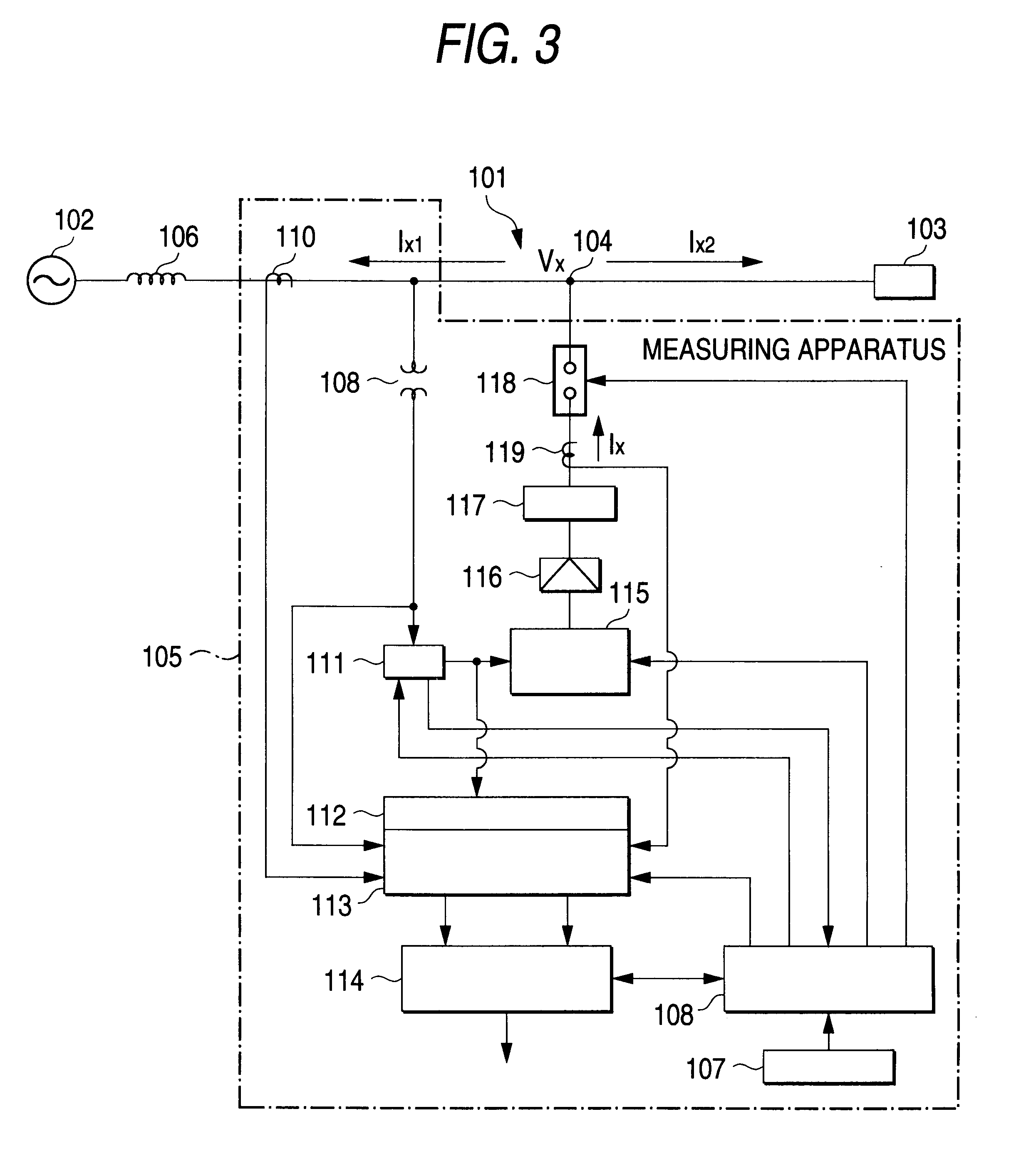
Next, a form will be discussed wherein a harmonic equivalent circuit in the power system 101 is a series circuit of an impedance and a voltage source and the impedance for the measurement harmonic on the upstream or downstream side or an equivalent circuit of series connection of the impedance and voltage source is found.
In this form, first the control section 108 performs an applied frequency determination process control similar to the applied frequency determination process control before measurement in FIG. 4 and FIG. 5.
The applied voltage frequencies fu and fd above and below the measurement harmonic are determined by executing the same process as steps S1-S13 in FIG. 4 and FIG. 5.
Next, control goes to measurement and the voltages of the determined frequencies fu and fd are applied to the harmonic inject point. The impedance and equivalent circuit for the measurement harmonic is found in the same manner as in the first embodiment.
In the same e...
third embodiment
[Third Embodiment]
A third embodiment of the invention will be discussed with reference to FIG. 7 to FIG. 12. The power system of FIG. 7 is similar to the power system of FIG. 1.
According to the third embodiment of the invention, an injecting technique of the injected currents above and below the measurement harmonic will be discussed.
First, equivalent circuits upstream and downstream from the harmonic inject point 204 for the nth-degree harmonic in the power system 201 can be assumed to be a parallel circuit of admittance Yn11 and a current source Gn11 and that of admittance Yn12 and a current source Gn12 as shown in equivalent circuits 219 and 220 in FIG. 8.
Equivalent circuits in the power system 201 for frequencies of nonintegral multiples of the fundamental wave above and below the nth-degree harmonic become admittance only because components of the frequencies originally do not exist.
Assuming that the power system 201 is a 1-KVA-based small capacity load circuit model easily cau...
PUM
 Abstract
Description
Claims
Application Information