
Apparatus and cooling system

a technology of cooling system and apparatus, applied in the direction of milking device, stationary tubular conduit assembly, lighting and heating apparatus, etc., can solve the problem that the arrangement would still have all the attendant disadvantages

Inactive Publication Date: 2001-04-10
AGMASTER AUSTRALIA
View PDF13 Cites 6 Cited by
  • Summary
  • Abstract
  • Description
  • Claims
  • Application Information

AI Technical Summary

Benefits of technology

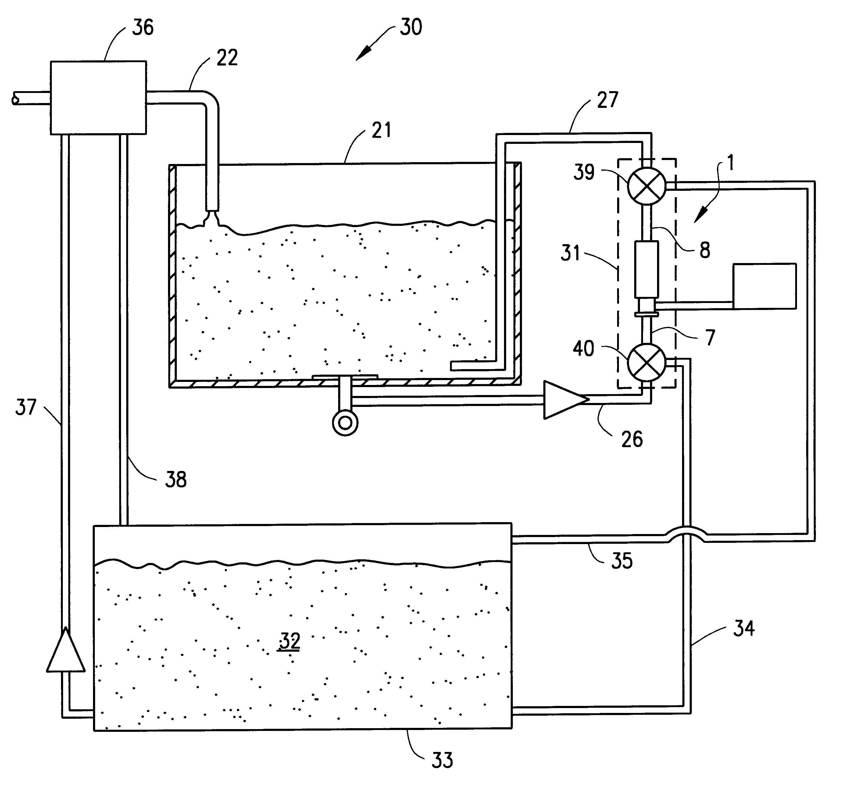
As can be appreciated from the above, the present invention diverges from known cooling systems in that pre-vat cooling need not be applied. The resulting isolation of the second flow path allows the cooling system of the invention to operate independently of fluid flow in the first flow path, thereby dispensing with the need one way for flow control valves in the second flow path. In addition, the specific construction of the cooling apparatus described above allows for ready inspection and cleaning of the apparatus, as compared with a known plate heat exchanger.

Problems solved by technology

In any event, the arrangement would still have all the attendant disadvantages when used in conjunction with a conventional plate heat exchanger in the above described system.

Method used


Image

  • Apparatus and cooling system
  • Apparatus and cooling system
  • Apparatus and cooling system

Examples


Embodiment Construction

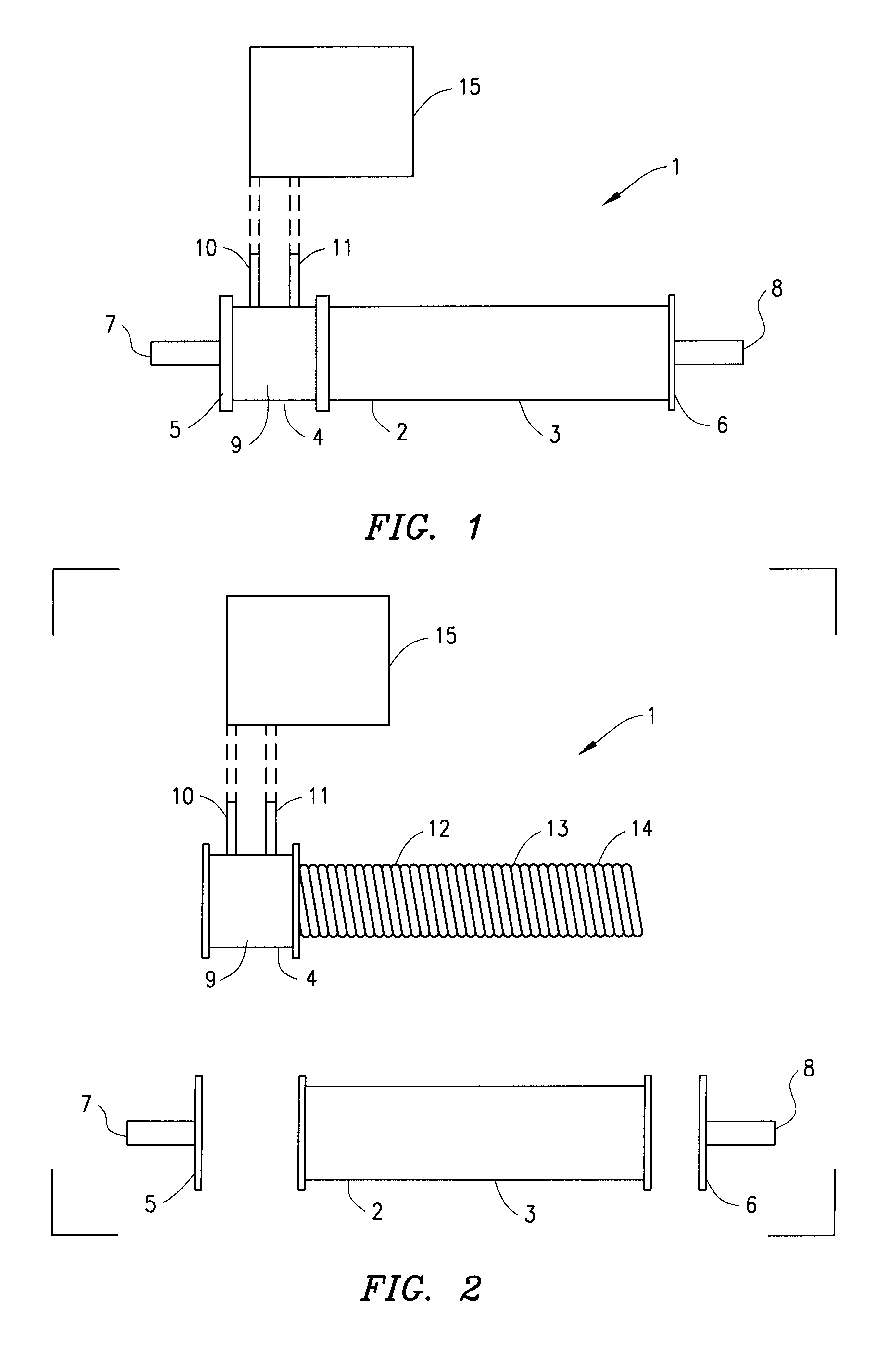
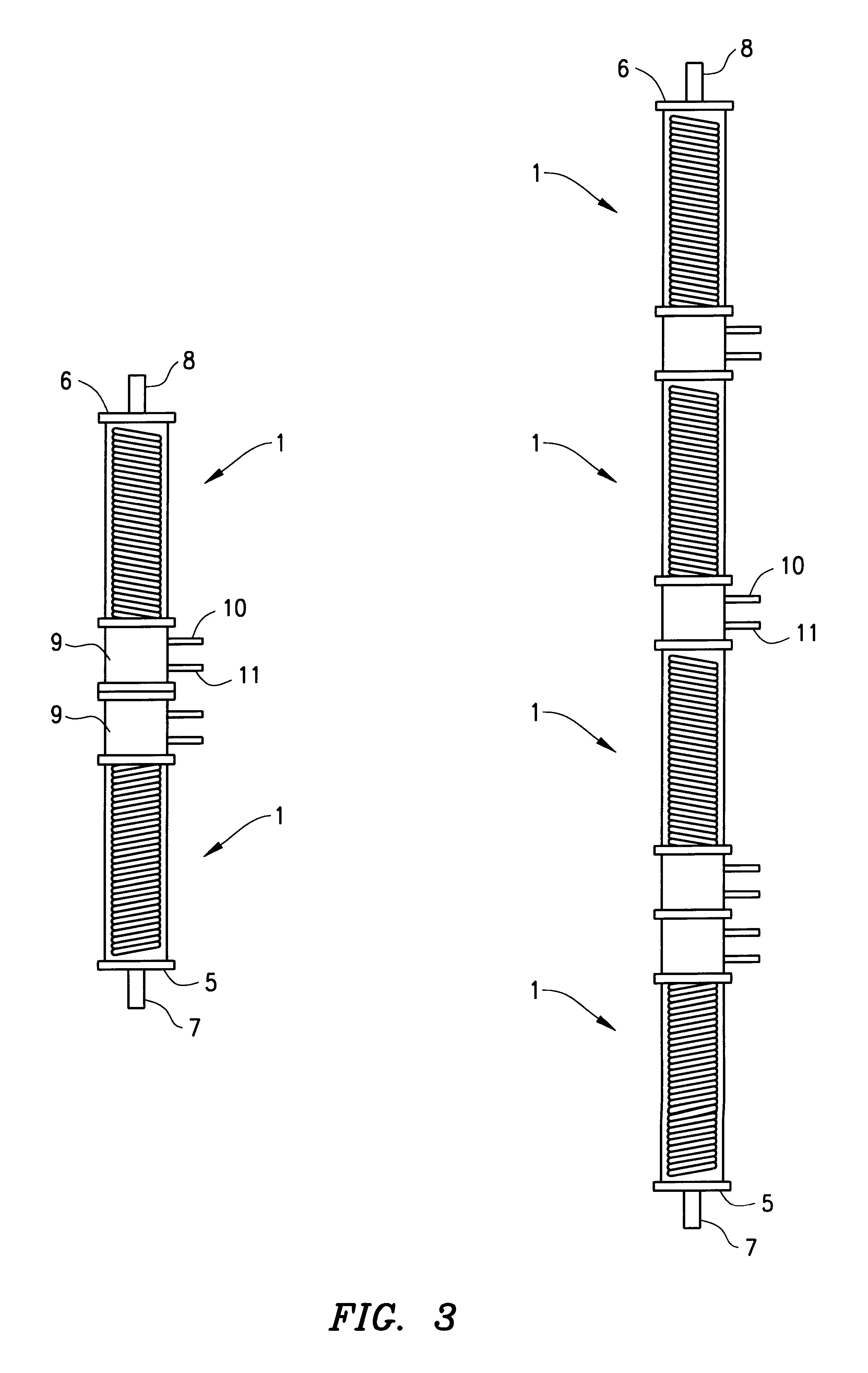
The apparatus 1 shown in FIGS. 1 and 2 includes a casing 2 in the form of a cylindrical sleeve 3, a cooling element 4 and end closure portions 5, 6 which define an inlet 7 and outlet 8 of the apparatus 1. The cooling element 4 includes a collar 9 with refrigerant inlet and outlet ports 10. 11 which are in fluid communication with a refrigerated element 12 which is formed of a tube 13 shape to define a generally hollow cylindrical coil heat exchanger 14. In use, refrigerant is pumped from a refrigeration unit 15 into the inlet port 10, through the tubing of the element 12 and out of the outlet port 11 to thereby refrigerate the coil. In this manner, liquid flowing from the inlet 7 to the outlet 8 will pass through and around the coil, in direct contact with the refrigerated clement 12 so as to be chilled to a desired temperature. The element 12 is preferably formed of stainless steel or is titanium plated so that it may be used with food grade liquid, such as milk. The curved surface...


PUM


Abstract

A cooling system particularly but not exclusively for cooling milk transferred for a milking station to a vat along a first flow path, the system including an apparatus for heat exchange with milk passing therethrough, wherein a second flow path is provided for circulating milk in the vat through the apparatus and the second flow path isolated from the first flow path.

Description

1. Field of the InventionThe present invention relates to an apparatus and cooling system particularly, but not exclusively, for use in the food or liquor industry.2. Description of the Related ArtA known form of cooling system which is utilized in the dairy industry includes a ply heat exchanger for cooling milk from dairy cows to a temperature of about 4.degree. C., to inhibit bacterial growth whilst the milk is in a storage vat awaiting transport to a milk tanker. The bottom of the vat may be formed of a second "dimple plate" heat exchanger which is cooled by refrigerant or chilled water to maintain the milk at a low temperature. A mechanical agitator may also be provided in the vat to circulate the milk so as to maximize efficiency of the dimple plate heat exchanger, prevent separation of the milk particles and also to prevent stratification of the milk.The plate heat exchanger is form of a plurality of thin plates which are connected in a sandwich type construction. Each plate ...

Claims


Application Information

Patent Timeline
Patent Type & Authority Patents(United States)
IPC IPC(8): A23C3/00A23C3/04A01J9/00A01J9/04F28F27/00F28F9/00F28D7/00F28D7/02F28F9/26
CPCA01J9/04A23C3/04F28D7/024F28F9/00F28F9/26F28F27/00F28F2280/02
Inventor WARD, DALE CAMERON
Owner AGMASTER AUSTRALIA
Learn More