Dielectric filter

a filter and dielectric technology, applied in the field of dielectric filters, can solve the problems of limited cost reduction by reducing the filter size, and limited manufacturing cost reduction by this approach

Inactive Publication Date: 2001-04-24
U S PHILIPS CORP
View PDF4 Cites 7 Cited by
  • Summary
  • Abstract
  • Description
  • Claims
  • Application Information

AI Technical Summary

Problems solved by technology

However, since the size of the filter itself directly relates to its frequency characteristic (particularly, its centre frequency), the reduc

Method used


Image

  • Dielectric filter
  • Dielectric filter
  • Dielectric filter

Examples


Embodiment Construction

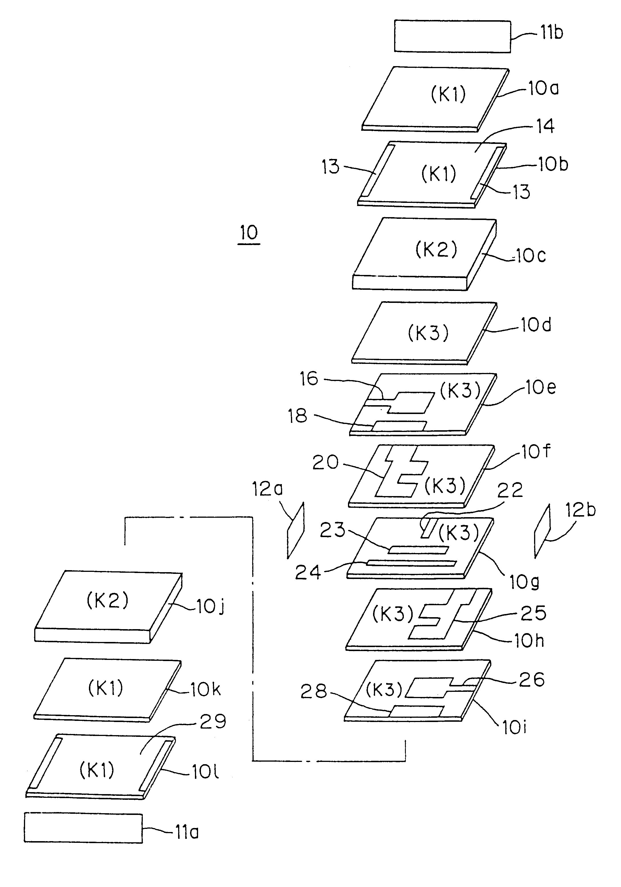
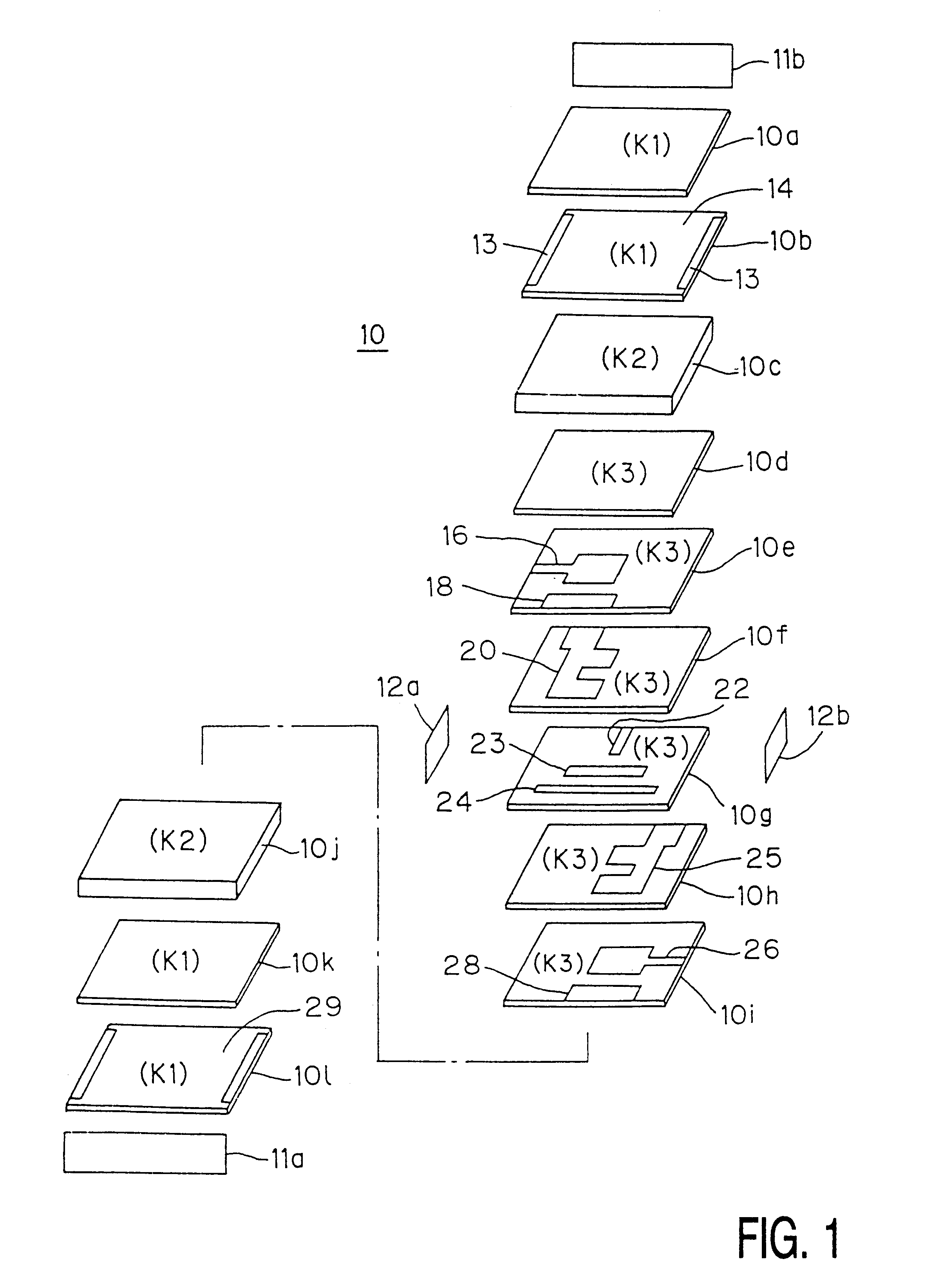
Conductive paste containing silver as its main component was applied, by means of silk screening, onto green sheets made of a ceramic material having a high dielectric constant, the material having a dielectric constant equal to 75 (K3=75) and containing barium titanate as its basis material. The paste on the green sheets was dried, whereby the electrodes 14; 16 and 18; 20; 22; 23 and 24; 25; 26 and 28 were formed. The green sheets with the electrodes thus formed thereon were combined with a predetermined number of green sheets without electrodes to form a respective one of the dielectric layers 10a to 10l. These dielectric layers were laminated and then simultaneously pressed and heated in a single sintering process, whereafter the electrodes 11a, 11b, 12a and 12b were formed on the respective sides to obtain a sample A for comparison. The thickness of the part consisting of the layers 10a and 10b was 100 .mu.m, that of the layer 10c 400.mu.m, that of the part consisting of the lay...


PUM


Abstract

A dielectric filter includes a first dielectric layer containing at least a pair of strip-line resonators to be electromagnetically coupled to each other. Second and third dielectric layers are disposed in an opposed relation to each other with the first dielectric layer sandwiched therebetween and having substantially the same dielectric constant (K1). Each of the second and third dielectric layers contains at least one shield electrode. The dielectric filter further includes fourth and fifth dielectric layers which have substantially the same dielectric constant (K2) and are interposed between the first and second dielectric layers and between the first and third dielectric layers, respectively. The dielectric constant (K2) of the fourth and fifth dielectric layers is selected to be less than any one of the dielectric constant (K1) of the second and third dielectric layers and the dielectric constant (K3) of the first dielectric layer.

Description

BACKGROUD OF THE INVENTIONThis invention relates to a dielectric filter suitable for use in high-frequency radio communication devices such as mobile phones and particularly to a miniature chip-type dielectric filter which is constructed by laminating a number of dielectric layers with electrodes sandwiched therebetween.There is an increasing demand, in the field of mobile phones and other handy radio communication devices, for further miniaturized high frequency filters, while such filters are required to meet both a high frequency selectivity and a low insertion loss. There has been proposed as a high-frequency filter which can meet the above requirements a multilayer ceramic filter which comprises stripline electrodes as resonators (i.e., a so-called stripline filter). For such multilayer ceramic filters, reference should be made, for example, to PCT WO 96 / 19843 and Japanese Patent Application Laid-Open No. 312503 / 95. A multilayer ceramic filter of this type is advantageous in th...

Claims


Application Information

Patent Timeline
IPC IPC(8): H01P1/203H01P1/20H01P1/205
CPCH01P1/20345H01P1/203H01P3/18
Inventor HORIE, KENICHIIWAYA, SHOICHI
Owner U S PHILIPS CORP
Why Eureka
Try Eureka