Protection scheme for multi-transistor amplifiers

a protection scheme and amplifier technology, applied in the direction of single-ended push-pull amplifiers, gain control, circuit arrangements, etc., can solve the problems of thermal runaway, the transistor with the highest temperature tends to carry more current, and the circuit designer's problems, etc., to achieve the effect of simple power devi

Inactive Publication Date: 2001-05-01
RPX CLEARINGHOUSE
View PDF1 Cites 16 Cited by
  • Summary
  • Abstract
  • Description
  • Claims
  • Application Information

AI Technical Summary

Benefits of technology

FIG. 3 is a circuit diagram of a power amplifier in accordance with the invention, and associated exciter and load for a simple power device.

Problems solved by technology

This parallel circuit arrangement creates some technical problems for circuit designers since a limited number of weak transistors are responsible for circuit failure.
However, when bipolar junction transistors are used, the transistors with the highest temperature tend to carry more current.
This can lead to a condition called thermal runaway.
It a transistor carries a little more current than the others in the circuit, it will also dissipate more power, which will tend to heat the transistor even more.
This self-heating operation can escalate until an over-current condition is reached and the transistor and amplifier circuits fail.
This is, unfortunately, not an optimal solution since it requires field replacement (i.e. substantial costs).
Also, for some integrated circuit technologies, a fuse would not protect the amplifier from damage during thermal runaway due to current hogging effects; and 3.
A disadvantage of this solution is that it would require a reset signal and possibly field maintenance (i.e. substantial costs).
Over-voltage breakdown: Any transistor has a maximum operating voltage, above which the device will cease to function properly and may be damaged, Typically, when the applied voltage exceeds the maximum operating voltage, the transistor enters an operating state where the device current is uncontrolled and extremely high.
This can lead to simultaneous over-voltage and over-current conditions.
In an integrated circuit, which contains several transistors, the maximum operating voltage of the individual devices will not be uniform.
On the other hand, in new or leading edge manufacturing processes, the voltage range will be relatively large due to material and process defects.
The problem that this creates is that the circuit's operation is limited by the weakest transistor.
The direct result in Lhis case is an increase in size of the amplifier circuit, hence an increase in costs.

Method used


Image

  • Protection scheme for multi-transistor amplifiers
  • Protection scheme for multi-transistor amplifiers
  • Protection scheme for multi-transistor amplifiers

Examples


Embodiment Construction

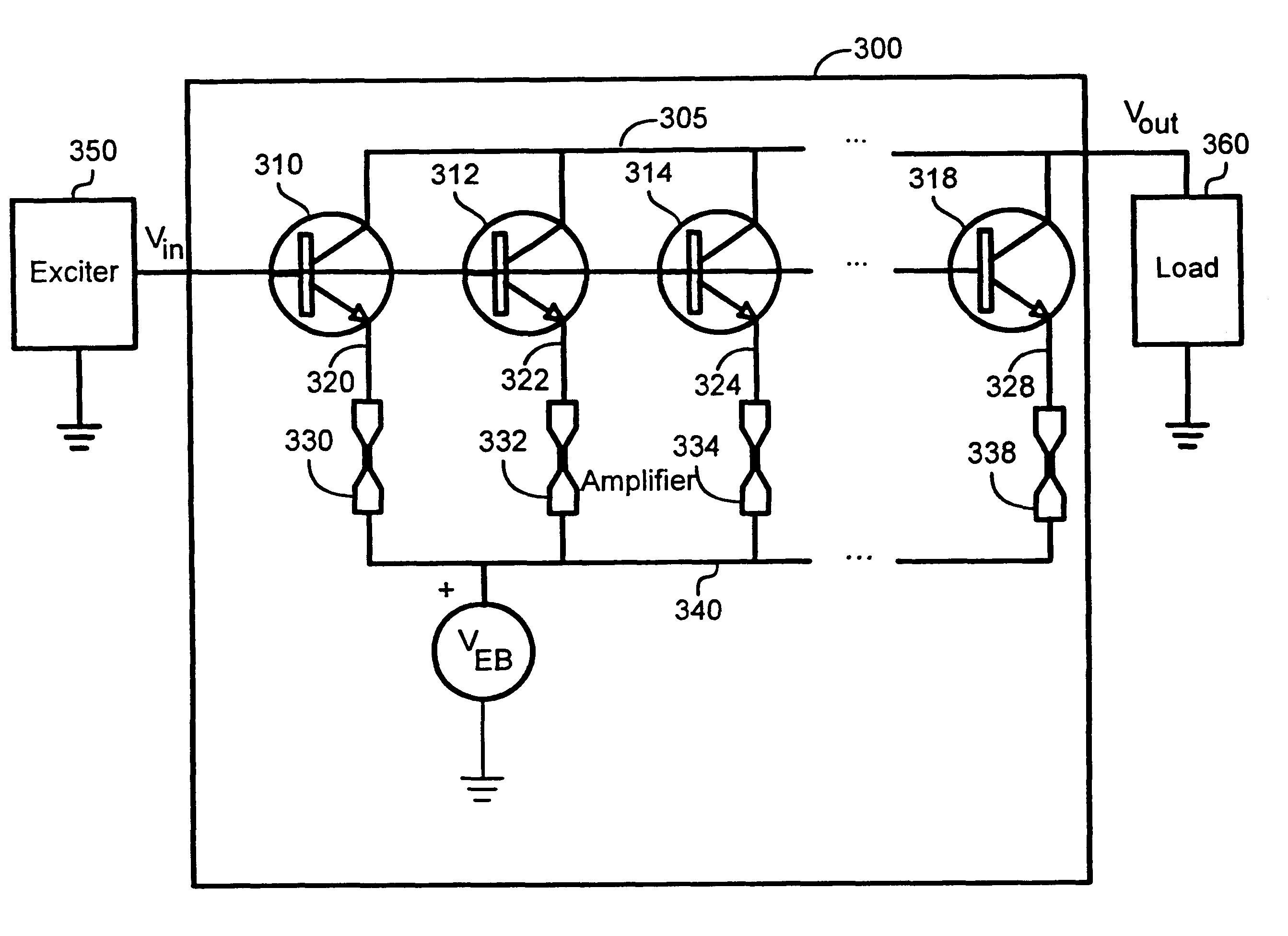
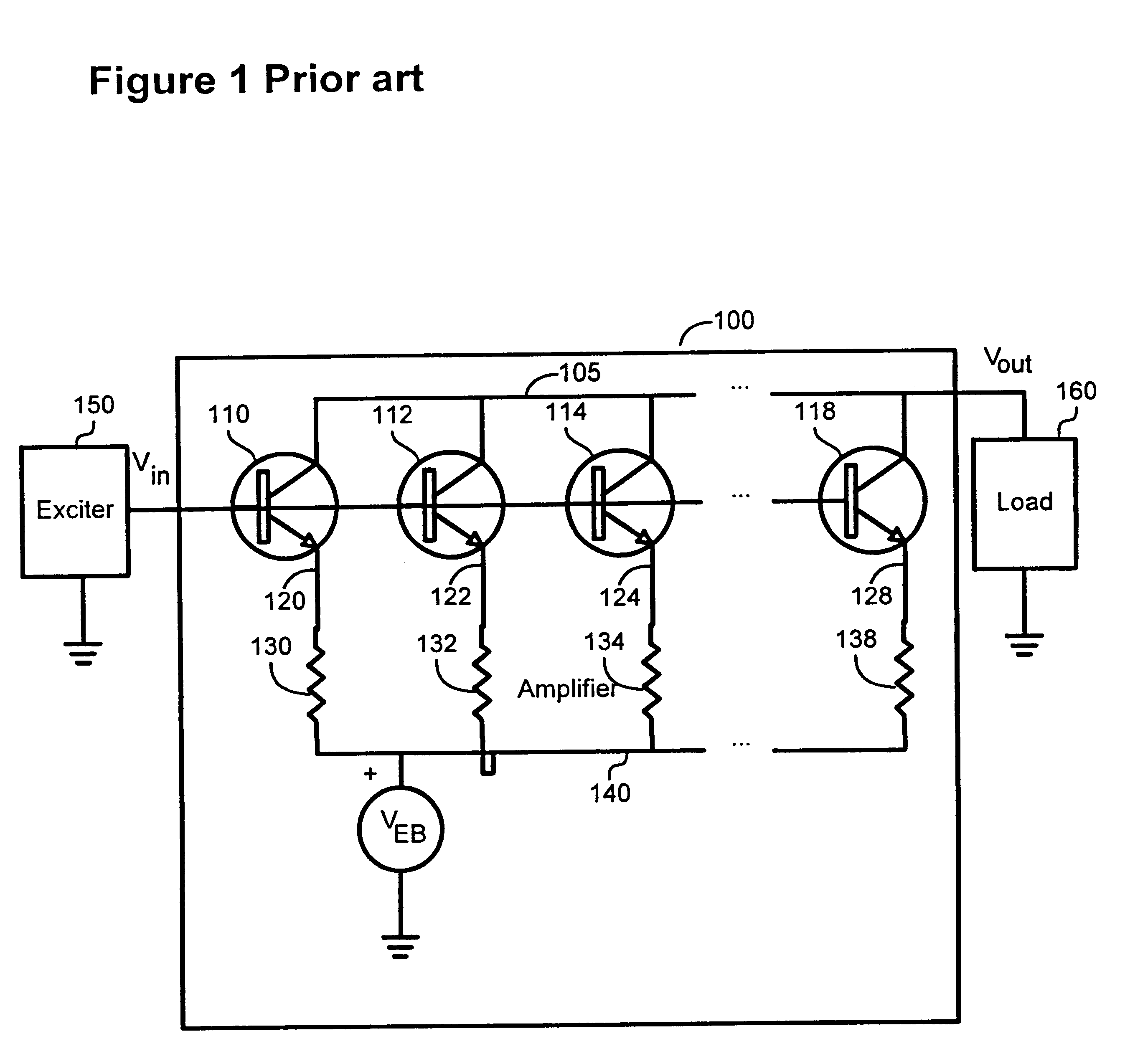
In many cases, power devices used in cellular telephony, and radio and television broadcasting are not a single transistor. Rather, they are composed of several power transistors connected in a parallel circuit arrangement as Shown in FIG. 1.

FIG. 1 shows a power amplifier 100, an exciter 150 and a load 160. The power amplifier is comprised of an array of power transistors 110, 112, 114 and 118 connected in parallel and a series of ballast resistors 130, 132, 134 and 138 connected to the emitter of each associated transistor through lines 120, 122, 124 and 128. The resistors are connected to the emitter bias Veb through line 140. The number of power transistors in one amplifier for the applications referred to herein is in the order of 200 to 1000. The input signal V.sub.in of the amplifier 100 is connected to the base of each transistor 110, 112, 114 and 118. The collector branches of each transistor are connected together through line 105 to provide the output of amplifier 100. Bal...


PUM


Abstract

The present invention deals with the problems related to thermal runaway and over-voltage breakdown in integrated circuits using a series of power transistors interconnected in a parallel circuit arrangement. The general technique described consists of a protection scheme that involves the application of a fusible material to form ballast resistor components. These components are connected in series with each of the transistors in the integrated circuits. The main advantages are significant area and cost savings in the manufacturing of the integrated circuits as well as an increase in their yield, thereby reducing costly field maintenance and equipment returns.

Description

The present invention relates to the large field of integrated circuit design. More specifically, it relates to resolving problems related to thermal runaway and over-voltage breakdown in integrated circuits involving interconnected power transistors.Power amplifiers are used to amplify electrical signals in a wide variety of applications including cellular telephony, and radio and television broadcasting. For power ranges of up to about 100 watts, the most common power device used in these amplifiers is a bipolar junction transistor (BJT). In many cases, the power device is not a single transistor, but is composed of several transistors connected in a parallel circuit arrangement. This parallel circuit arrangement creates some technical problems for circuit designers since a limited number of weak transistors are responsible for circuit failure. Two of these problems, thermal runaway and over-voltage breakdown, are further explained below.Thermal runaway: In an amplifier that is ma...

Claims


Application Information

Patent Timeline
Patent Type & Authority Patents(United States)
IPC IPC(8): H03F1/52H03F1/30
CPCH03F1/302H03F1/52H03F2203/21178
Inventor ILOWSKI, JOHNKUNG, WILLIAM
Owner RPX CLEARINGHOUSE
Why Eureka
Try Eureka