Method of inverter control and apparatus of the same

a technology of inverter and control apparatus, which is applied in the direction of electric generator control, dynamo-electric converter control, dynamo-electric gear control, etc., can solve the problem of reducing the accuracy of estimated current value, reducing the price of inverter system, and disadvantageously required to collect motor constants

Inactive Publication Date: 2001-05-08
HITACHI LTD
View PDF4 Cites 68 Cited by
  • Summary
  • Abstract
  • Description
  • Claims
  • Application Information

AI Technical Summary

Problems solved by technology

However, this method requires motor current sensors or detectors for two phases and accordingly current sensor circuits for two phases.
This soars the price of the inverter system.
For each type o...

Method used


Image

  • Method of inverter control and apparatus of the same
  • Method of inverter control and apparatus of the same
  • Method of inverter control and apparatus of the same

Examples


Embodiment Construction

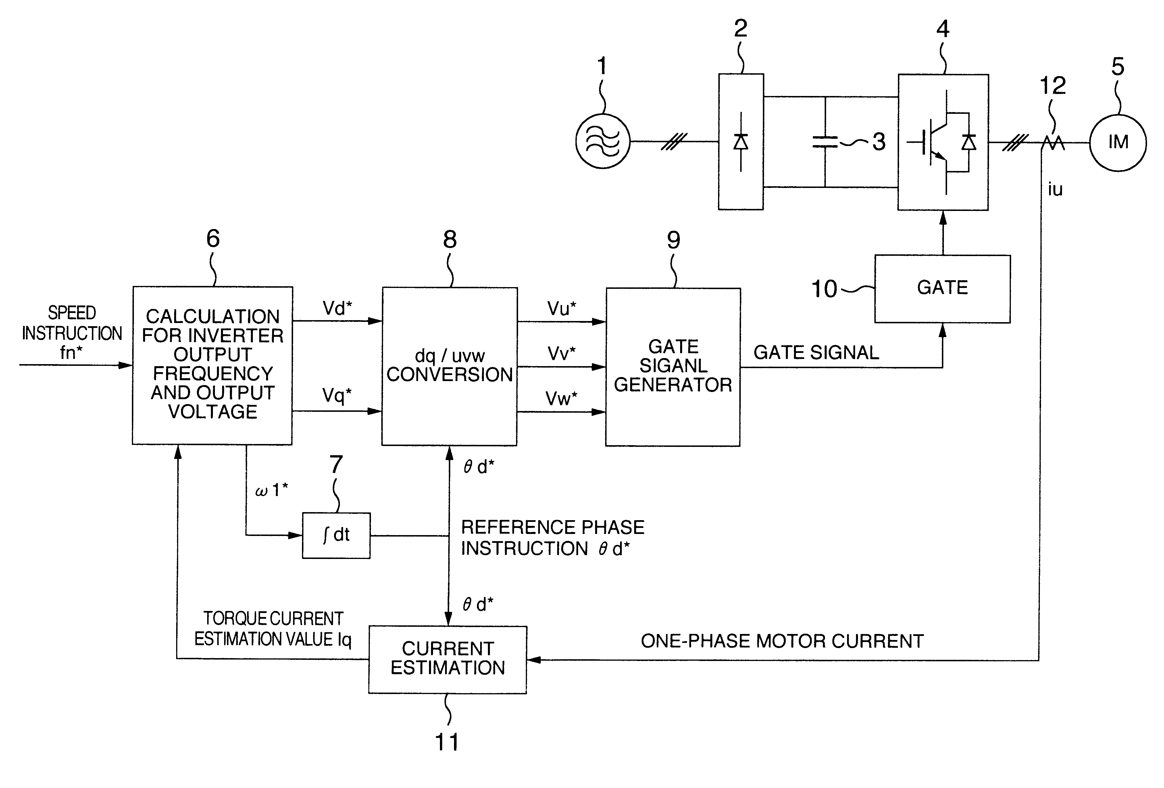
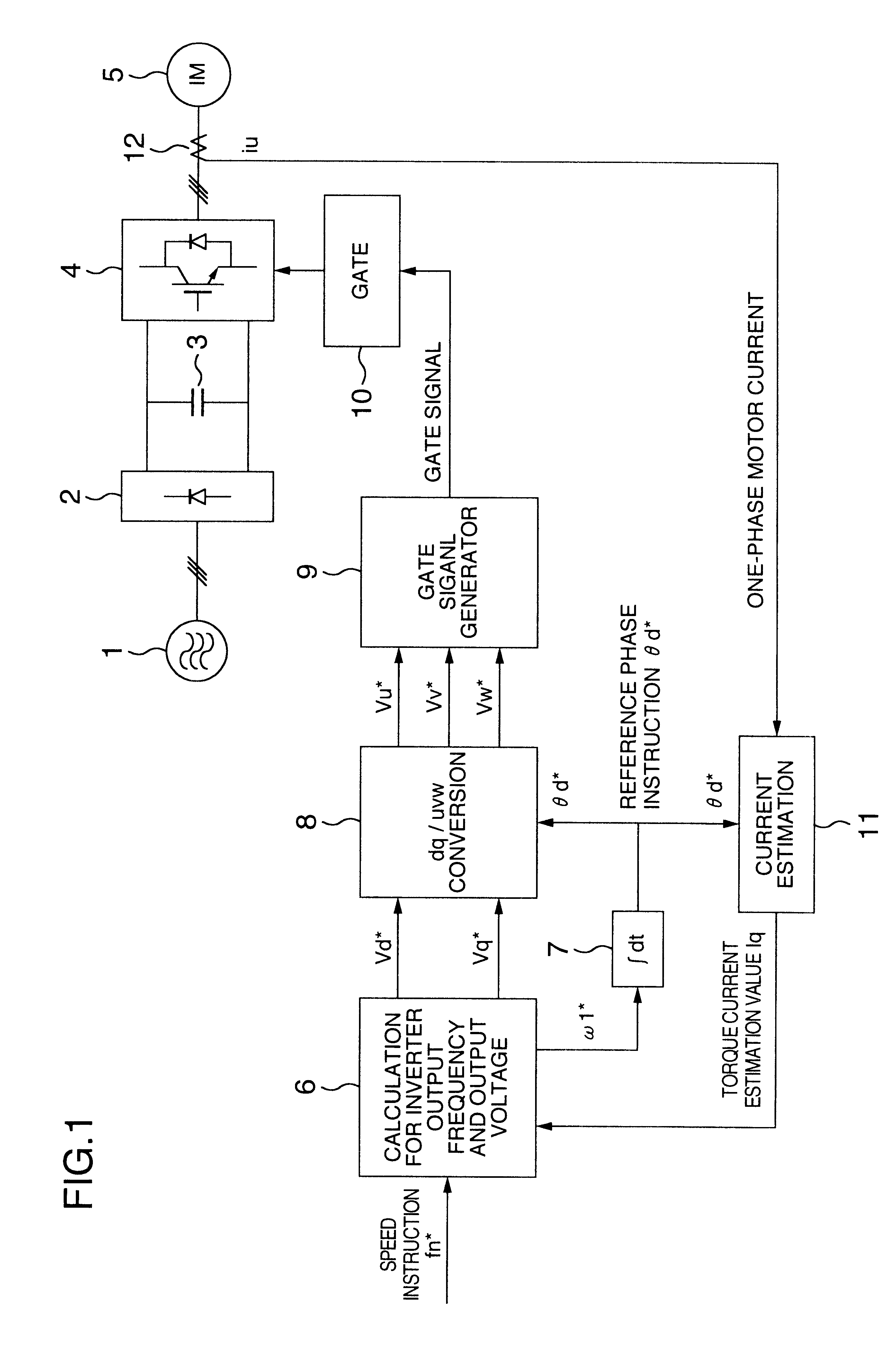
Referring now to the drawings, description will be given of an embodiment of an inverter control system of the present invention. FIG. 1 shows in a block diagram of an inverter control block to control an alternating-current (ac) motor at a variable speed. In this system, an alternating current from an ac power source 1 is transformed by a rectifier circuit 2 and a smoothing condenser 3 into a direct current (dc). The dc power is converted by an inverter 4 into an alternating current having a variable frequency and a variable voltage to drive an induction motor 5 at a variable speed. The output frequency and the output voltage of the inverter 4 are controlled by the inverter control circuit via a gate circuit 10.

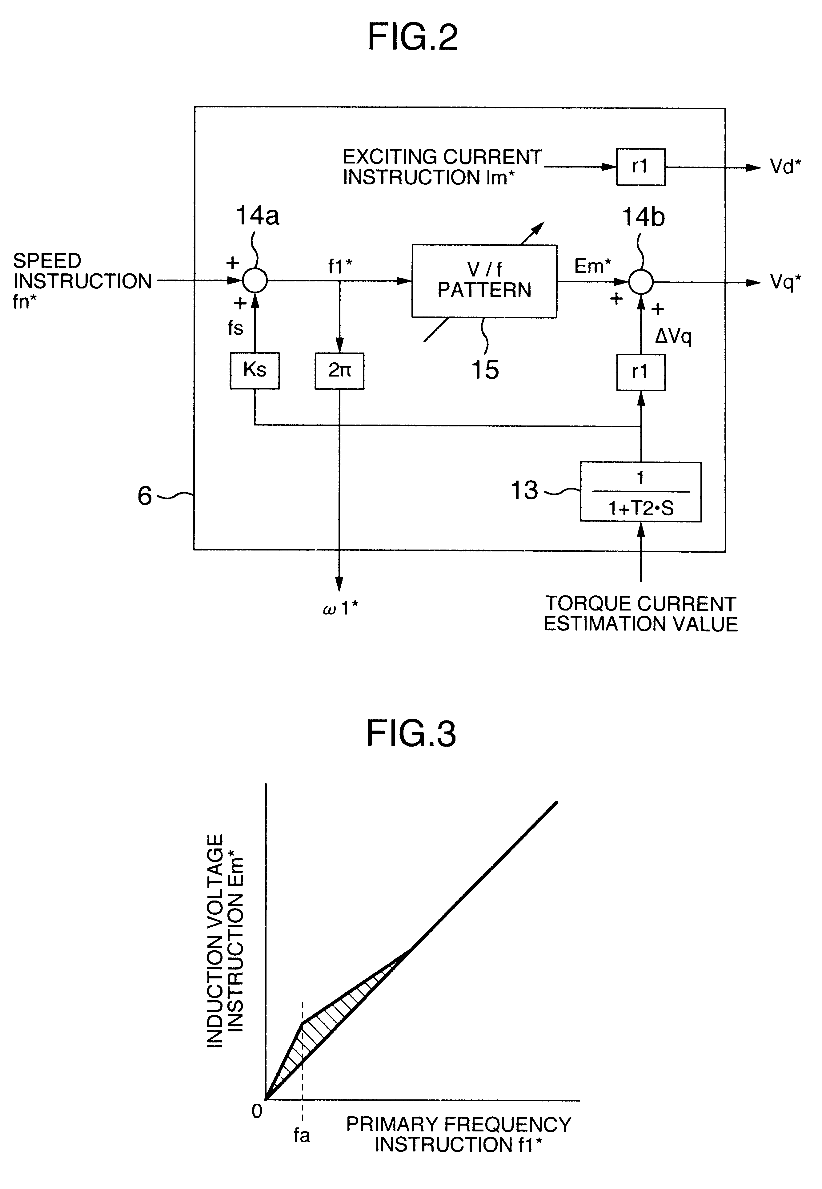
The inverter control circuit of this embodiment includes an inverter output frequency and voltage calculating section 6 which receives a speed instruction fn* and a torque current estimation value Iq of an induction motor under consideration to calculate a primary angular fr...


PUM


Abstract

An inverter control apparatus includes an instruction calculator which receives a speed instruction and a particular component of a current of a motor to obtain an output frequency instruction and output voltage instructions of an inverter and a current estimator to estimate, according to a reference phase obtained by integrating a current detection value of one phase of an ac motor and an output frequency instruction thereof, currents of other phases of the ac motor. The current estimator includes a uvw/dq converter which converts a fixed coordinate system into a rotating coordinate system, a dq/uvw converter which is connected to the uvw/dq converter and which converts the rotating coordinate system into the fixed coordinate system, and a closed loop to input an output from the dq/uvw converter to the uvw/dq converter. This system can therefore estimate currents of other phases according to the motor current of one phase.

Description

1. Field of the InventionThe present invention relates to a method of and an apparatus for controlling an inverter which drives an induction motor at a variable speed, and in particular, to an automatic torque boost control method and an automatic torque boost control apparatus.2. Description of the Related ArtIn a known method to control an inverter to drive an induction motor at a variable speed, an output voltage V1 of the inverter is controlled in proportion to a primary frequency f1 of the inverter, i.e., V / f is kept fixed. The exciting current of an induction machine can be kept almost fixed in this method. However, when a load imposed onto the motor is increased, the voltage drop due to primary resistance 1 of the motor becomes greater and an induction or induced voltage of the motor is minimized. Resultantly, the exciting current of the motor is reduced and torque of the motor is lowered. Since an actual speed is lowered in response to a speed instruction, the speed regulati...

Claims


Application Information

Patent Timeline
IPC IPC(8): H02P21/00H02P21/14H02P27/04H02P21/18H02P21/22H02P21/24H02P23/07
CPCH02P21/0035H02P21/0042H02P21/146H02P21/22H02P21/26H02P21/18
Inventor SAKAI, KEIJIROOKUYAMA, TOSHIAKIFUJII, HIROSHI
Owner HITACHI LTD
Why Eureka
Try Eureka