This helps you quickly interpret patents by identifying the three key elements:
Problems solved by technology
Method used
Benefits of technology
Benefits of technology
It is an another object of the present invention to provide a heat pump cycle system which improves heating capacity while improving coefficient of performance during heating operation.
According to the present invention, a heat pump cycle system includes a compressor for compressing refrigerant, a case for forming therein an air passage through which air flows toward a compartment, a first heat exchanger disposed in the case for performing heat exchange between air inside the case and refrigerant flowing therein, a second heat exchanger disposed outside the case for performing heat exchange between air outside the case and refrigerant flowing therein, a refrigerant pipe forming a refrigerant passage through which refrigerant in the first heat exchanger and refrigerant in the second heat exchanger communicate with each other, an expansion valve disposed in the refrigerant passage for reducing pressure of refrigerant, and a switching unit for switching a communication between a discharge port of the compressor and an inlet of the first heat exchanger and a communication between the discharge port of the compressor and an inlet of the second heat exchanger. In the heat pump cycle system, the compressor discharges refrigerant with a pressure higher than the critical pressure, the first heat exchanger includes a plurality of first heat-exchanging portions arranged in line relative to a flow direction of air flowing through the air passage, the first heat-exchanging portions of the first heat exchanger are connected in line relative to a flow direction of refrigerant flowing therein, and one of the first heat-exchanging portions, at a most downstream side relative to the flow direction of air, is placed at a most upstream side relative to the flow direction of refrigerant during the heating operation. Thus, a lower limit temperature of air blown from the first heat exchanger can be increased, and the temperature of air from the first heat exchanger into the compartment can be increased.
Preferably, the expansion valve is controlled based on temperature of refrigerant in any a position from a refrigerant outlet of a most upstream heat-exchanging portion and a refrigerant inlet of a most downstream heat exchanging portion relative to the flow direction of refrigerant during the heating operation. Therefore, an opening degree of the expansion valve can be controlled based on a relatively high temperature of refrigerant, and the heat pump cycle system is controlled so that the discharge pressure of the compressor becomes higher even when the control of expansion valve during the heating operation is the same as that during the cooling operation. Thus, the control of the expansion valve can be made simple, while the heat pump cycle system prevents both the heating capacity and the coefficient of performance from being deteriorated.
More preferably, the heat pump cycle system further includes a control unit for controlling an opening degree of the expansion valve. The control unit includes a temperature setting unit for setting a temperature of the compartment, an air temperature sensor for detecting a temperature of air before flowing into the first heat exchanger, and a target pressure determining unit for determining a target pressure of refrigerant discharged from the discharge port of the compressor during the heating operation based on the temperature detected by the air temperature sensor and the temperature set by the temperature setting unit, so that coefficient of performance becomes approximately maximum. In the heat pump cycle system, the control unit controls the opening degree of the expansion valve in such a manner that pressure of refrigerant discharged from the compressor becomes the target pressure. Thus, the heat pump cycle system can perform the heating operation while preventing the coefficient of performance from being deteriorated.
Problems solved by technology
However, when the pressure of high-pressure side refrigerant is simply increased, coefficient of performance of the CO.sub.2 refrigerant cycle is deteriorated.
However, the conventional CO.sub.2 refrigerant cycle is only for increasing the cooling capacity of the CO.sub.2 refrigerant cycle.
As a result, when the control of the cooling operation is simply applied to the heating operation in the conventional CO.sub.2 refrigerant cycle, the coefficient of performance during the heating operation is deteriorated.
In this case, because it is necessary to increase the pressure of CO.sub.2 refrigerant discharged from the compressor, the coefficient of performance of the CO.sub.2 refrigerant cycle may be deteriorated.
Method used
Image
Click on the blue label to locate the original text in one second.
Reading with bidirectional positioning of images and text.
Examples
first embodiment
Next, operation of the heat pump cycle system according to the present invention will be now described.
(1) Cooling Operation
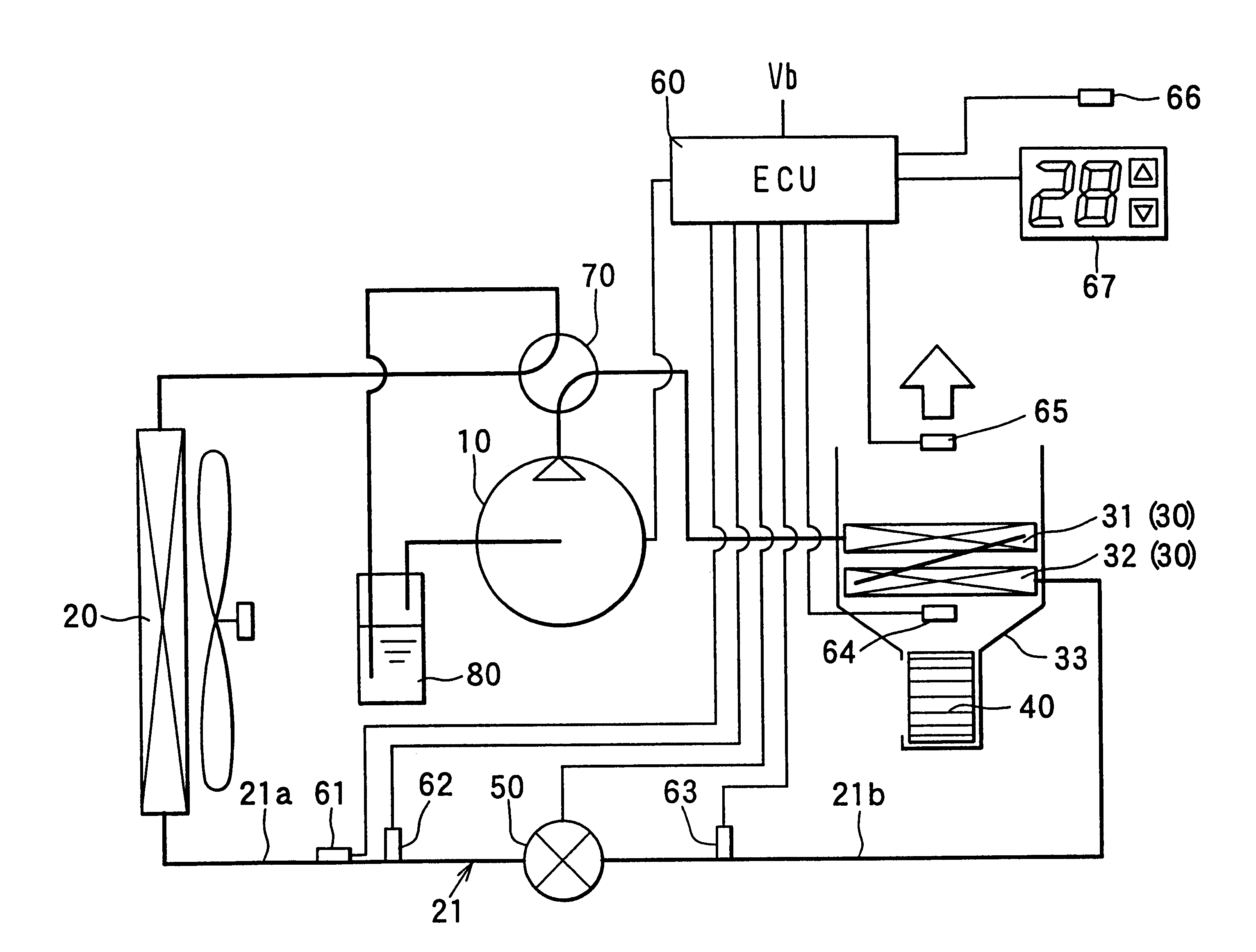
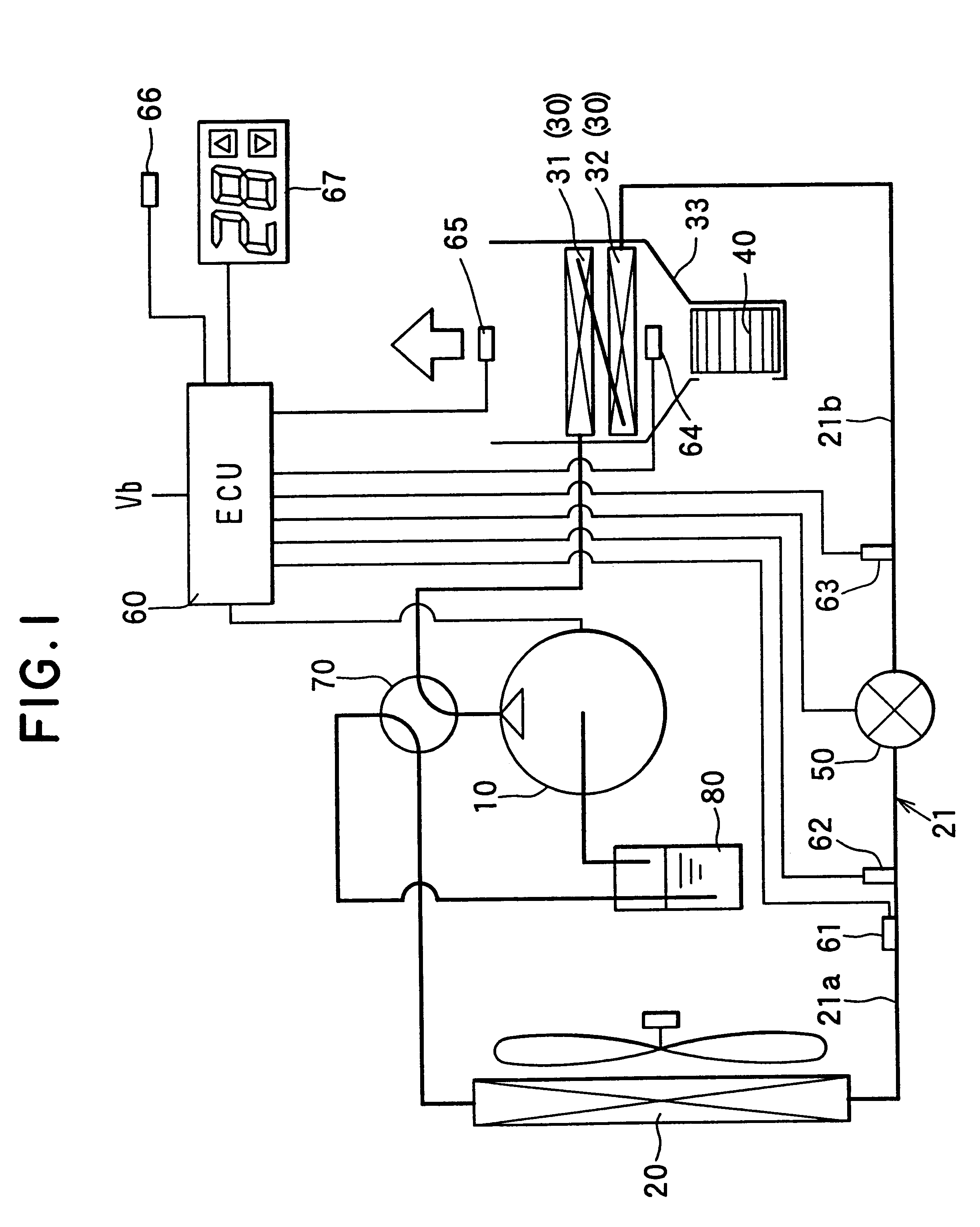
During the cooling operation, as shown in FIG. 3, refrigerant discharged from the compressor 10 is cooled in the outside heat exchanger 20, is decompressed in the expansion valve 50, is evaporated in the inside heat exchanger 30 by absorbing heat from air in the air conditioning case 33, and is sucked into the compressor 10 after passing through the accumulator 80. Therefore, air passing through the inside heat exchanger 30 is cooled during the cooling operation. In this case, pressure of refrigerant (i.e., high-pressure side refrigerant) on an outlet side of the outside heat exchanger 20 is controlled by the expansion valve 50 based on the temperature of refrigerant on the outlet side of the outside heat exchanger 20, detected by the first temperature sensor 61.
Here, the control of the expansion valve 50 will be now described in detail based on the flow diagra...
third embodiment
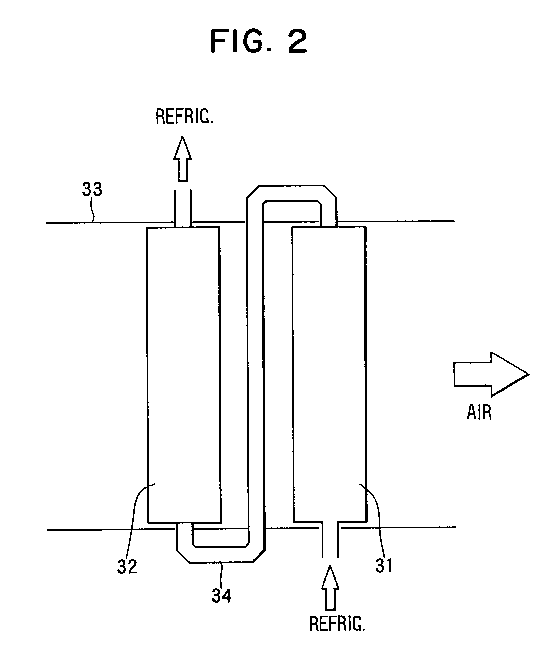
FIG. 14 is a schematic view showing a CO.sub.2 refrigerant cycle of a heat pump cycle system according to the As shown in FIG. 14, the second temperature sensor 64 described above is omitted, and a fifth temperature sensor 68 is disposed to detect the temperature of refrigerant flowing in a refrigerant pipe 34 connecting the refrigerant outlet side of the first inside heat exchanger 31 and the refrigerant inlet side of the second inside heat exchanger 32.
Here, the control of the expansion valve 50 according to the third embodiment will be now described based on the flow diagram shown in FIG. 15. Firstly, at step S400, refrigerant temperature detected by the first temperature sensor 61 is input during the cooling operation or refrigerant temperature detected by the fifth temperature sensor 68 is input during the heating operation. Next, at step S410, a target pressure is determined based on the relationship between the refrigerant temperature and the refrigerant pressure, shown in F...
fourth embodiment
An initial load of the coil spring 620 is adjusted by a spacer 621, so that a predetermined initial load applied to the valve body 618 is adjusted by the spacer 621. In the present invention, the initial load of the coil spring 620 is about 1 MPa when being calculated by the pressure of the diaphragm 611.
FIG. 18 is a schematic view of the mechanical expansion valve 500. The structure of the expansion valve 500 is similar to that of the expansion valve 600, except for the refrigerant passage 602 forming a part of the refrigerant pipe 34. That is, as shown in FIG. 18, a sealed space 512 is formed by a spherical-surface valve cover 510 and a diaphragm 511. CO.sub.2 refrigerant is sealed within the sealed space 512 by a density of about 600 kg / m.sup.3 when a valve port 517 is closed. A refrigerant inlet side space 514 and a refrigerant outlet side space 515 of the expansion valve 500 are partitioned by a partition wall portion 516, and a valve port 517 through which both spaces 514, 515...
PUM
Abstract
A heat pump cycle system which can switches cooling operation and heating operation for a compartment includes a first inside heat exchanger and a second inside heat exchanger disposed in an air conditioning case. The first inside heat exchanger is disposed in the air conditioning case at a downstream air side of the second inside heat exchanger, while being arranged in line in a flow direction of refrigerant. The first inside heat exchanger is upstream from the second inside heat exchanger in the flow direction of refrigerant during the heating operation. In the heat pump cycle system, an expansion valve is controlled so that coefficient of performance in each operation becomes approximately maximum. Thus, during the heating operation of the heat pump cycle system, a lower limit temperature of air blown from the inside heat exchangers can be increased so that temperature of air blown into the compartment is increased, while the coefficient of performance is improved.
Description
This application is related to and claims priority from Japanese Patent Applications No. Hei. 10-237450 filed on Aug. 24, 1998 and No. Hei. 11-196349 filed on Jul. 9, 1999, the contents of which are hereby incorporated by reference.1. Field of the Invention:The present invention relates to a heat pump cycle system in which pressure of refrigerant discharged from a compressor exceeds the critical pressure and carbon dioxide (CO.sub.2) is used as refrigerant. The heat pump cycle system can set cooling operation and heating operation.2. Description of Related Art:A vapor-compression type refrigerant cycle using carbon dioxide (CO.sub.2) as refrigerant (hereinafter, referred to as "CO.sub.2 refrigerant cycle") is disclosed in JP-A-9-264622 by the applicant of the present invention. To increase cooling capacity of the CO.sub.2 refrigerant cycle, pressure of high-pressure side refrigerant is need to be increased. However, when the pressure of high-pressure side refrigerant is simply incre...
Claims
Application Information
Patent Timeline
Application Date:The date an application was filed.
Publication Date:The date a patent or application was officially published.
First Publication Date:The earliest publication date of a patent with the same application number.
Issue Date:Publication date of the patent grant document.
PCT Entry Date:The Entry date of PCT National Phase.
Estimated Expiry Date:The statutory expiry date of a patent right according to the Patent Law, and it is the longest term of protection that the patent right can achieve without the termination of the patent right due to other reasons(Term extension factor has been taken into account ).
Invalid Date:Actual expiry date is based on effective date or publication date of legal transaction data of invalid patent.

