
Electrode assembly and method for signaling a monitor

a technology of electrodes and monitors, applied in the field of electrode assembly and method for signaling a monitor, can solve the problems of impracticality of devices for patients under anesthesia, patient under anesthesia may not have had reliable eye movements or even any purposeful eye movements, etc., and achieve the effect of quick and accurate placement of electrodes

Inactive Publication Date: 2001-05-15
PATIENT COMFORT
View PDF18 Cites 80 Cited by
  • Summary
  • Abstract
  • Description
  • Claims
  • Application Information

AI Technical Summary

Benefits of technology

Accordingly, it is an object of the present invention to provide a device which allows for quick and accurate placement of electrodes upon the tissue of a living animal to monitor differential electrical states.
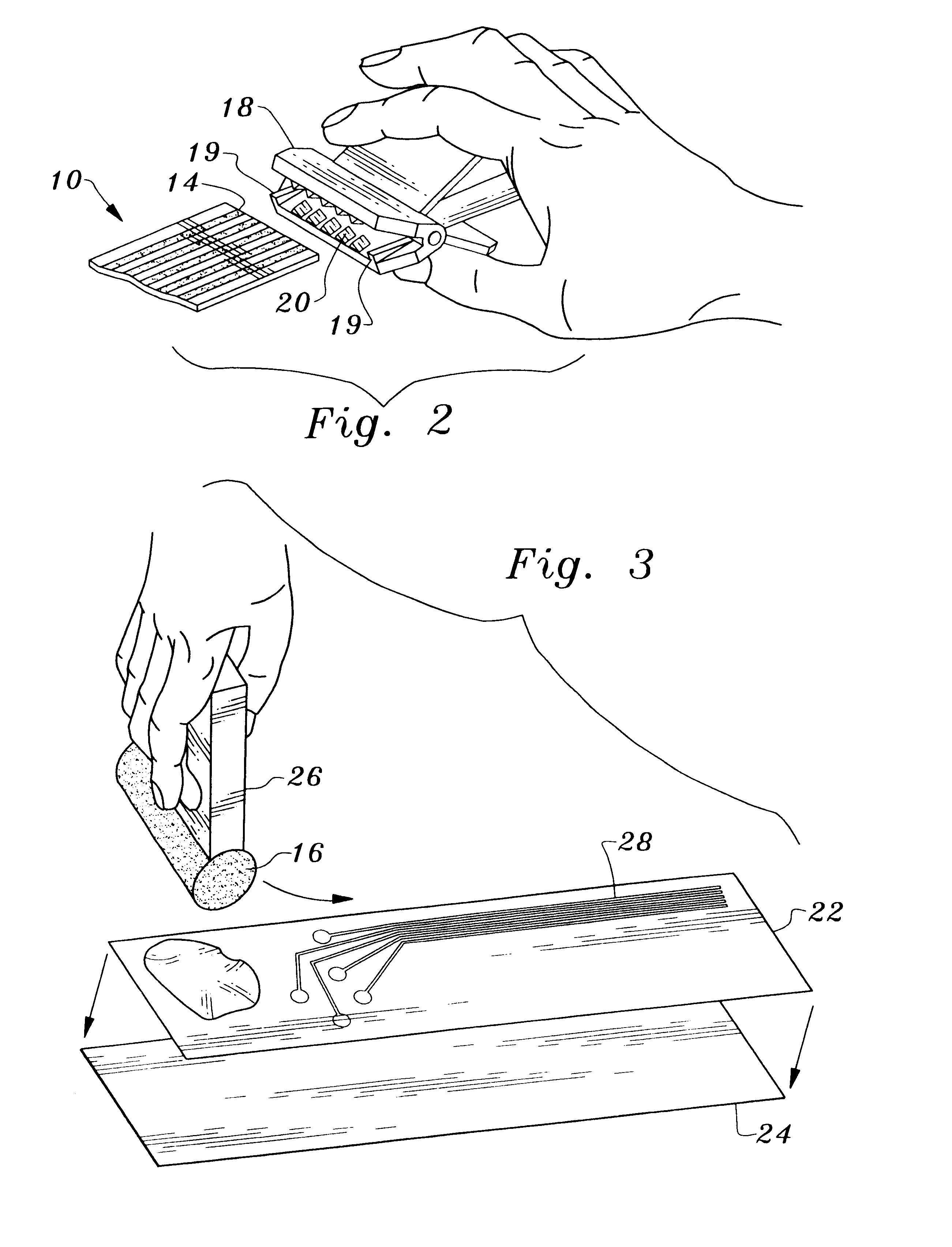
Another object of the present invention is to provide an electrode assembly which is easily and economically manufactured by well-known techniques such as silk-screen or ink type printing process.
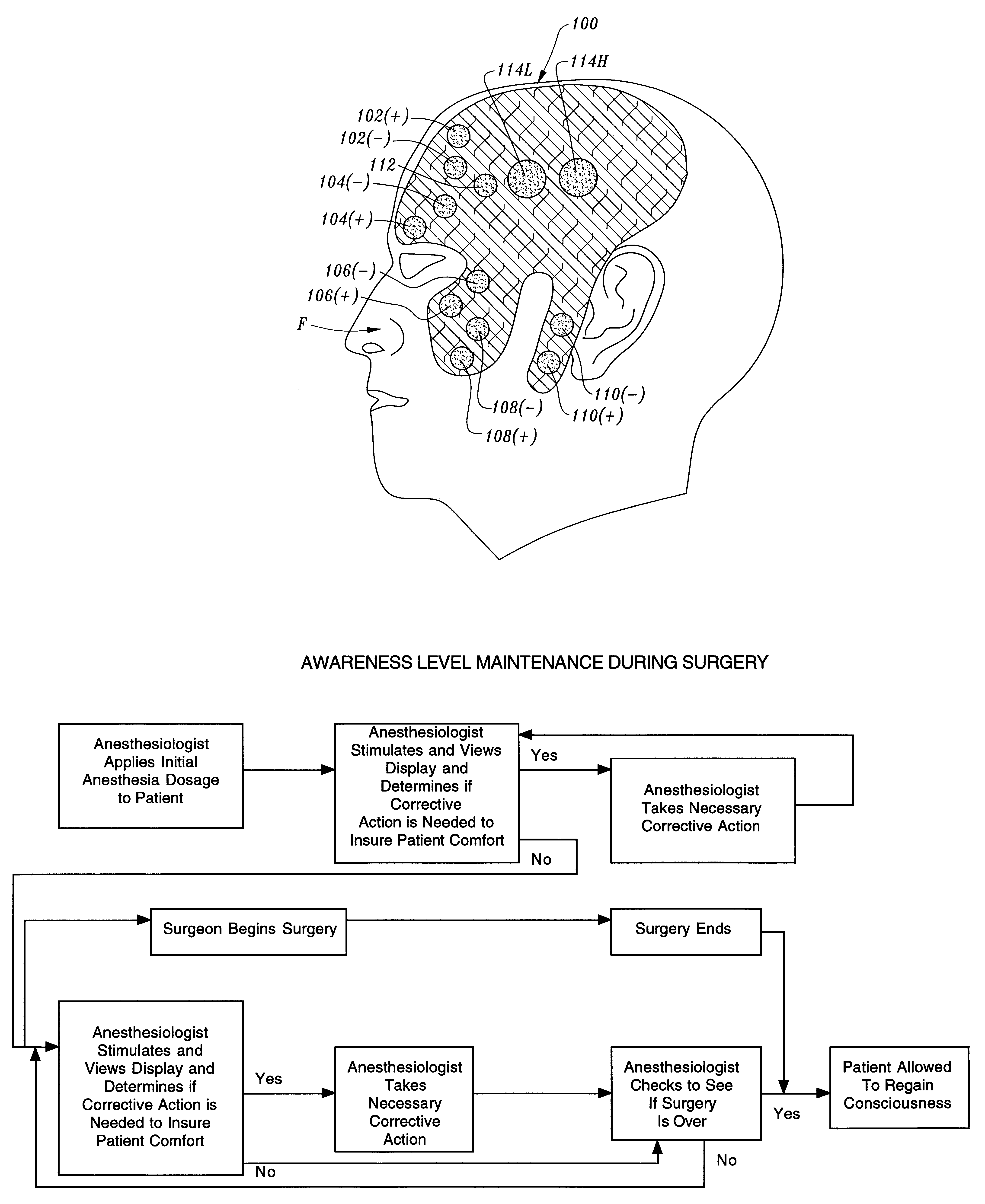
Another object of the present invention is to provide a sensing means preconfigured to pick up signals from certain facial muscle groups that will serve as a reliable indicator of the level of awareness of a patient undergoing anesthesia wherein the same preconfiguration arrangement of electrodes can be used with different individuals.
Yet another object of the present invention is to provide for an electrode assembly of substantially uniform thickness which assures that when the assembly is in between the patient's tissue and a bed pillow or mattress or surgery table that no pressure points are developed during the monitoring of the patient.
Viewed from a second vantage point it is the object of the present invention to provide a method for maintaining an appropriate level of patient awareness under anesthesia, the steps including: providing at least one electrode assembly, comprising a flexible layer, a pattern of electrically conductive material, disposed upon one side of the flexible layer wherein the pattern contains as at least two electrodes and is adapted to be connected to a signal receiving means, a non-conducting adhesive that electrically isolates at least one electrode from another electrode, but allows at least two electrodes to contact the tissue of said patient; and attaching the assembly to the face of the patient, picking up a signal with the electrodes, receiving the signal in a processing device through a signal receiving means, processing the signal received from the electrodes to determine what facial expression the signal represents by comparing the signals from different electrodes, the signals being reflective of the patient's facial muscle tonus, displaying the processed signal for viewing by an anesthesiologist on a display, anesthetizing the patient with an initial dosage of anesthetic to create muscle relaxation in a desired level of awareness, and controlling the patient's level of awareness and analgesia.

Problems solved by technology

A patient under anesthesia may not have had reliable eye movements or even any purposeful eye movements at all.
Because the patient must hold the electrode device against his face, this device was impractical for a patient under anesthesia.
Problems remained with the manufacture of the second described electrodes because of the care necessary to assure that the conducting gel coated only the discs, that the insulating coat necessary to avoid contact between the circuits and the patient's skin was completely protective, and the necessity of hooking the six conductor cable to the connector edge tab.

Method used


Image

  • Electrode assembly and method for signaling a monitor
  • Electrode assembly and method for signaling a monitor
  • Electrode assembly and method for signaling a monitor

Examples


Embodiment Construction

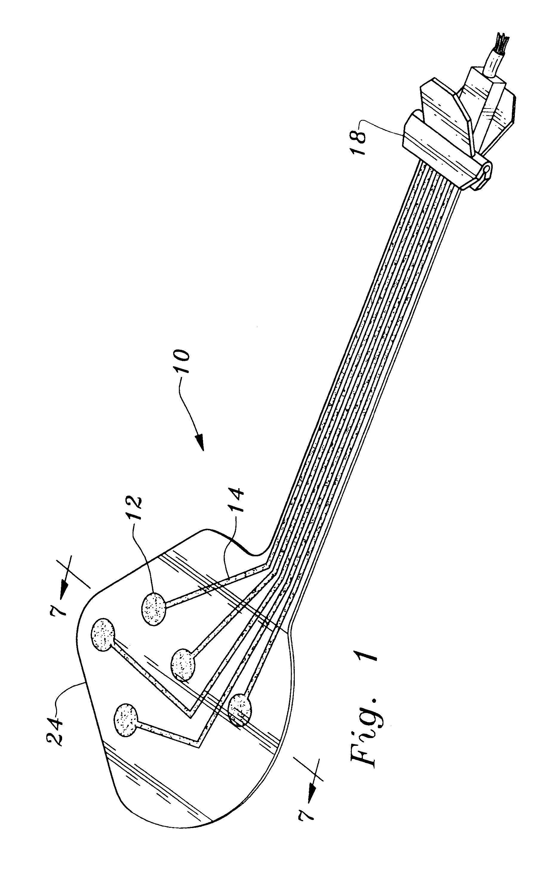
Considering the drawings, wherein like reference numerals denote like parts throughout the various drawing figures, reference numeral 10 is directed to a two-muscle electrode assembly according to the present invention. Referring now to FIG. 1, an electrode assembly 10 is shown engaged with spring biased signal input clamp 18. Leading from electrode contact points 12 are electrical connecting paths 14 which carry any signal received by electrode contact points 12 to spring biased signal input clamp 18. The electrode contacts points 12 and electrical connecting paths 14 are disposed upon flexible layer 24. Flexible layer 24 can be made from any of a number of flexible plastic substrates. Depending on the type of plastic used, the thickness of the flexible layer can vary from 1 mil to 3 mil, preferably being 2 mil for preferred plastic. A preferred embodiment of electrode assembly 10 uses one type of plastic that is a combination of vinyl and mylar plastics. Going on now to FIG. 2, sp...


PUM


Abstract

An electrode assembly adapted to be attached to the skin over selected facial muscle groups picks up signals to be analyzed by an anesthesia adequacy monitor that measures the level of awareness of a living animal, typically a human being. The electrode assembly also includes a stimulator that stimulates a facial nerve to determine the level of paralysis, or neuro muscular block, of the facial muscles. Also disclosed is a method of manufacturing the electrode assembly by printing a pattern of electrically conductive material through a silk-screen or an ink type process onto a flexible layer, and then coating the result with a non-conducting adhesive except at points corresponding to sensing points for the desired muscle groups. Finally, a method for using such sensing and stimulating devices is shown in determining and maintaining an appropriate level of patient awareness, muscle paralysis, and analgesia under anesthesia.

Description

The following invention relates to devices which are used in the field of assessment of consciousness of a person, electromyography, and specifically for measuring the clinical condition of a patient under anesthesia by noting the muscular activity related to facial micro-expressions. This invention is also concerned with a method for determining the adequacy of anesthesia, and the level of paralysis therefrom, during surgery and otherwise through stimulating and measuring the muscular activity of the face. This method and this device allows for quick application of stimulating and multiple sensing means for the different muscles in the face.INCORPORATION OF SPECIFICATION BY REFERENCEU.S. Pat. No. 5,195,531 describing an anesthesia adequacy monitor and method, was issued to Henry L. Bennett on March 23, 1993. The disclosure of U.S. Pat. No. 5,195,531 (the "First Bennett Patent") is specifically incorporated herein by reference.In the past, when the face was stimulated and monitored ...

Claims


Application Information

Patent Timeline
Patent Type & Authority Patents(United States)
IPC IPC(8): A61B5/0488A61B5/0492A61B5/0408A61B5/296
CPCA61B5/0492A61B5/4821A61B5/04085A61B5/4041A61B2562/0217A61B5/282A61B5/296
Inventor BENNETT, HENRY L.CRAM, JEFFREY R.SIMON, BRUCE JAY
Owner PATIENT COMFORT
Learn More