Ultrasonic inspection apparatus and method using a focused wave device

a focused wave device and ultrasonic inspection technology, applied in the direction of counting objects on conveyors, instruments, specific gravity measurements, etc., can solve the problems of structural failure of composite doubler installations, cracks, disbonding, dents and gouges, etc., to improve the conventional ultrasonic inspection of structures, increase the distance traveled, and increase the distance traveled by the transmitted

Inactive Publication Date: 2001-05-22
SANDIA NAT LAB
View PDF3 Cites 78 Cited by
  • Summary
  • Abstract
  • Description
  • Claims
  • Application Information

AI Technical Summary

Benefits of technology

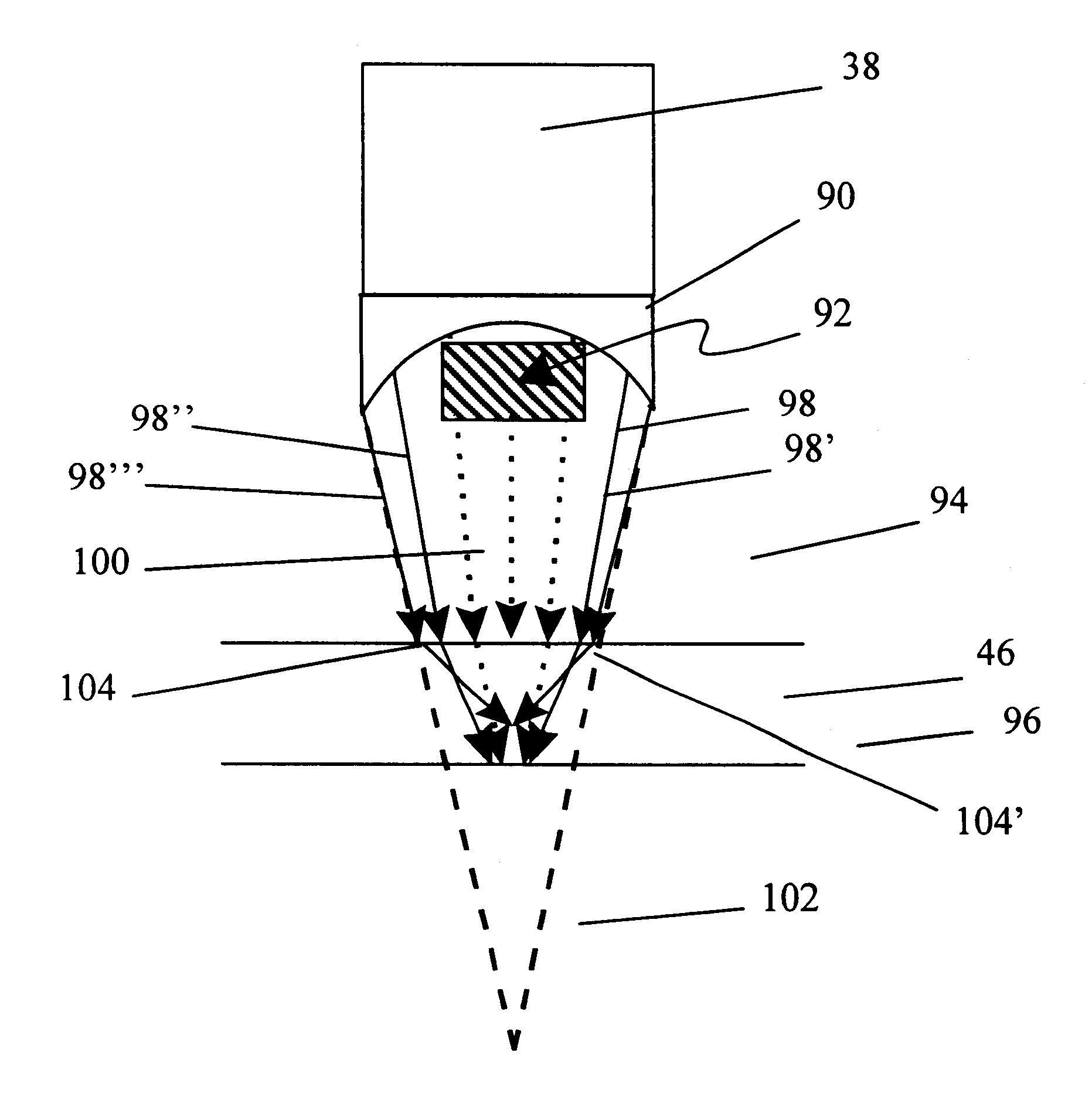
The present invention is an apparatus and method for improving conventional ultrasonic inspections of structures. In the preferred embodiment, a transducer is used to create an ultrasonic signal and a stop is oriented to block selected waves of the ultrasonic signal. Most preferably a focus lens is used to focus the ultrasonic signal upon the desired area of the structure to be inspected. A scanning system is used to control the transducer and collect reflected ultrasonic data from the transducer. A couplant, such as water, is used to aid in coupling the ultrasonic signal between the transducer and structure. A scanning shoe can be used to increase the distance traveled by the ultrasonic signal. The ultrasonic transducer preferably has a diameter of at least approximately 0.5 inches, and most preferably of approximately 1.0 inch, and operates between approximately 0.1 and 25 megahertz, most preferably five megahertz. The focus lens is conductive and refractive of ultrasonic waves and...

Problems solved by technology

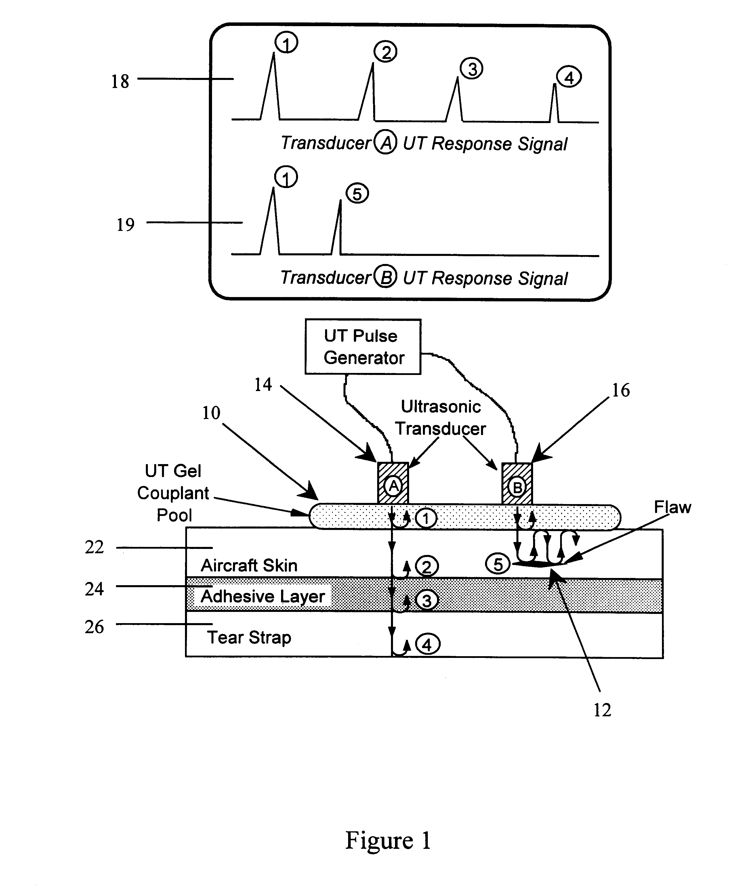
The unavoidable by-product of this use is that flaws develop throughout the aircraft's skin and substructure elements.
These flaws can take the form of cracks, corrosion, disbonds, dents, and gouges.
In particular, identification of disbonds between the doubler and the aluminum skin and delaminations within the composite are important since these defects prevent the doubler from performing as designed.
The two main potential causes of structural failure in composite doubler installations are cracks in the...

Method used


Image

  • Ultrasonic inspection apparatus and method using a focused wave device
  • Ultrasonic inspection apparatus and method using a focused wave device

Examples


example

In this example, the ultrasonic inspection apparatus and inspection method using a modified focus transducer was used to identify disbonds between a composite doubler and the aluminum skin of an aircraft fuselage. A study to assess the performance capabilities of composite doublers was chosen on an L-1011 aircraft for reinforcement of the upper right corner of a cargo doorframe of the fuselage. For this application, a boron-epoxy composite doubler, or repair patch, of 72 plies was installed.

The elements of the Boron-Epoxy composite doubler are shown in FIG. 7 where the thickness dimensions are greatly exaggerated to illustrate the lay-up construction of the composite. The aluminum skins where the doublers are normally installed range in thickness from 0.04 to 0.07 inch. A typical application of a composite doubler or repair patch is shown for the case of a fatigue crack repair. Aluminum skin 114 is connected to boron-epoxy doubler 110 by adhesive layer 112. Structural damage 116, fo...


PUM


Abstract

An ultrasonic pulse echo inspection apparatus and method for detecting structural failures. A focus lens is coupled to the transducer to focus the ultrasonic signal on an area to be inspected and a stop is placed in the focus lens to block selected ultrasonic waves. Other waves are not blocked and are transmitted through the structure to arrive at interfaces therein concurrently to produce an echo response with significantly less distortion.

Description

1. Field of the Invention (Technical Field)The present invention relates to ultrasonic inspection of structural failures particularly for detecting disbonds or delaminations.2. Background ArtOne of the primary goals of the Federal Aviation Administration's (FAA) National Aging Aircraft Research Program (NAARP) is to foster new technology associated with the repair of civil aircraft. A typical aircraft can experience over 2,000 fatigue cycles (cabin pressurizations) and many more flight hours in a single year. The unavoidable by-product of this use is that flaws develop throughout the aircraft's skin and substructure elements. These flaws can take the form of cracks, corrosion, disbonds, dents, and gouges.Composite doublers, or repair patches, provide a repair technique that can enhance the way aircraft are maintained. The high modulus of Boron-Epoxy composite material enables a doubler to pick up load efficiently and effectively when bonded to a metal structure. The load transfer oc...

Claims


Application Information

Patent Timeline
IPC IPC(8): G01N29/22G01N29/24G10K11/00G10K11/30
CPCG01N29/221G01N29/223G01N29/2456G10K11/30G01N2291/044
Inventor GIESKE, JOHN H.ROACH, DENNIS P.WALKINGTON, PHILLIP D.
Owner SANDIA NAT LAB
Why Eureka
Try Eureka