Anti-static cleanroom products and methods of making same

a technology of anti-static cleanroom products and cleanroom products, applied in carpet cleaners, other chemical processes, weaving, etc., can solve the problems of increasing static electricity problems, affecting the production yield of reliable semiconductor devices, and loose particles less than 100 micrometers in size, and achieves uniform anti-static properties, simple and inexpensive to make and us

Inactive Publication Date: 2001-05-22
ILLINOIS TOOL WORKS INC
View PDF23 Cites 20 Cited by
  • Summary
  • Abstract
  • Description
  • Claims
  • Application Information

AI Technical Summary

Benefits of technology

In particular, it is an object to provide cleanroom products such as wipers which have relatively uniform anti-static properties, without degradation of the cleanroom quality of the products.
It is a further object of the present invention to provide such cleanroom products and manufacturing methods which are relatively simple and inexpensive to make and use.
In accordance with the invention, cleanroom products are provided with a coating of conductive polymeric particulates. The particulates decrease the surface resistivity of the products to give them anti-static characteristics, without degrading the cleanroom properties of the products.

Problems solved by technology

In this regard, items which are subject to abrasion or wear are a cause of special concern since such abrasion and wear can result in particle formation.
Loose particles 100 micrometers and smaller in size are an anathema to obtaining high production yields and reliable semiconductor devices.
The problem of static electricity has become an ever increasing problem where, for example, sensitive electronic equipment is being manufactured.
Control of static electricity can be critical in many industrial or commercial settings where an undesired electrostatic discharge (ESD) or spark can result in serious damage.
For example, in explosive environments such as in grain elevators or in flammable environments such as an oil drilling rig or refinery, a spark can be extremely dangerous.
In addition, static discharge can damage sensitive integrated circuits.
One particularly significant problem is the fact that the average person will not sense a discharge of less than 3500 volts.
Since many electronic devices can be damaged by potentials far lower than 3500 volts, such devices can be damaged unknowingly and incorporated into the final product.
As a result, the final product will be defective, without anyone knowing it.
However, the use of such fibers has many disadvantages.
Furthermore, conductive fibers may be relatively brittle when compared to the majority of fibers used in a wiper product and therefore have a tendency to break when flexed.
Such breakage not only results in a reduction in the static dissipative capability of the material, but also provides a source of contamination to the cleanroom environment.

Method used


Image

  • Anti-static cleanroom products and methods of making same
  • Anti-static cleanroom products and methods of making same
  • Anti-static cleanroom products and methods of making same

Examples


example 1

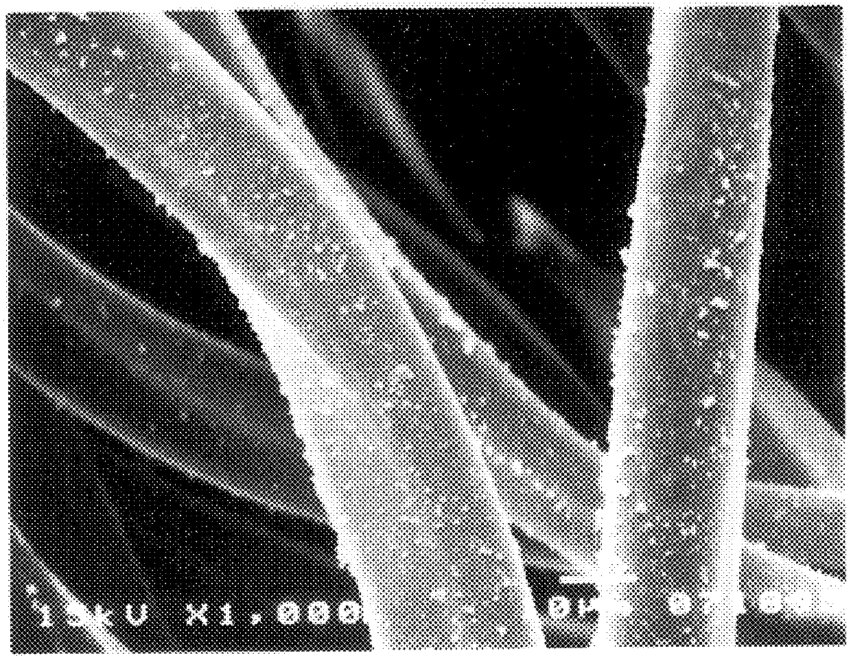
300 mL of deionized water was placed in a 1.5 L beaker. The beaker placed on the platform of an orbital shaker running at a speed of 150 rpm. 2.0 g of benzenesulfonic acid, sodium salt and 2.8 g of ferric chloride were slowly added into the beaker after both ingredients were predissolved separately in 50 mL water. Immediately after the additions, 0.5 g of neat pyrrole (non-diluted) was added dropwise into the beaker. While the shaker was still running, 12.2 g of polyester wiper material was added to the beaker. The total weight represented two 9".times.9" sealed-edge double-knit wipers constructed from 100 percent continuous filament textured polyester.

The reaction was run for two hours at room temperature. Initially the color of the white wipers changed to light yellow and then gradually changed to grayish black. At this stage, the wipers were taken out from the beaker and placed in a separate clean beaker. The wipers were then rinsed several times with deionized water containing a...
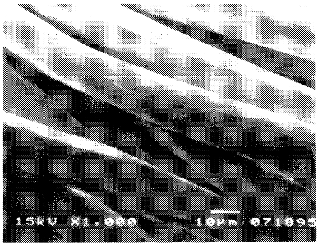
example 2

provided three important findings. First, nylon material coats more rapidly than polyester in this process (in terms of time needed for the application of the coating). Second, ferric chloride should be avoided as the oxidizing agent if chloride concentration is a concern since it causes the higher chloride contamination in the product. Third, the resultant particulate coating adheres strongly to the fibers.
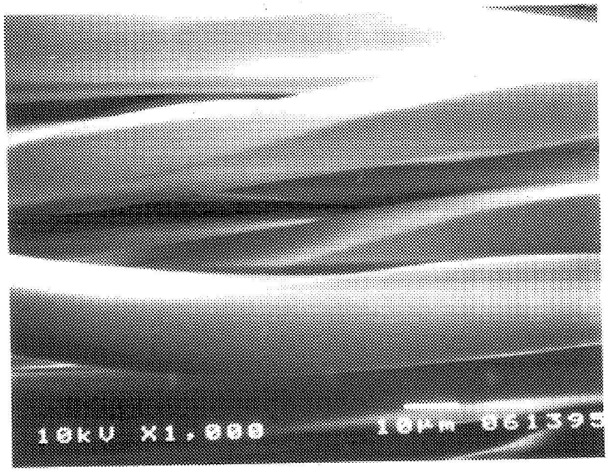
example 3

The procedure of Example 2 was repeated except the contents of the steel tray as shown in Example 2 were changed as follows:

a. 900 mL deionized water

b. 0.5 g of 2,6-Napthalenedisulfonic acid, disodium salt as the doping agent predissolved in 50 mL water

c. 0.5 g of Potassium persulfate as the oxidizing agent predissolved in 50 mL water

d. 1 mL of neat pyrrole added dropwise

e. and 4 pieces of 9".times.9" nylon wipers.

The reaction was run at room temperature. The entire content of the tray was allowed to shake on an orbital shaker for 30 minutes. The resultant products were grayish black wipers. The wipers were taken out and rinsed several times with deionized water containing surfactants and allowed to dry. The dried wipers were tested and found to be as clean as those prepared in Example 2, including a substantial reduction in chloride content. The resistivity was tested and determined to be in the range of 10.sup.+6 .OMEGA.. The chloride content in these wipers was low and quantified...


PUM

PropertyMeasurementUnit
sizeaaaaaaaaaa
sizeaaaaaaaaaa
timeaaaaaaaaaa

Abstract

Anti-static cleanroom products having a coating of conductive polymeric particulates which decreases the surface resistivity of the products. Preferably, the particulates are pyrrole polymers. The anti-static properties are achieved by depositing conductive polymer particles onto the non-conductive substrate surface. The anti-static products include cleanroom wipers, stationery products (notebooks and writing instruments), garments and swabs (polyurethane foam tipped). The cleanroom stationery products include notebooks comprising polyethylene impregnated with silica. The invention also includes anti-static plastic gloves.

Description

1. Field of the InventionThis invention relates generally to the prevention of particulate contamination and static-discharge in cleanrooms. More specifically, this invention relates to anti-static products used in "cleanrooms", semiconductor fabrication plants, pharmaceutical manufacturing facilities, and other applications and environments where extreme cleanliness must be maintained, and to methods for making such products.2. Description of the Related ArtCleanrooms are being used more often in a greater variety of areas. The requirements for maintaining cleanliness in semiconductor fabrication cleanrooms, pharmaceutical manufacturing facilities and similar facilities, for example, are stringent. Products brought into and used in cleanroom environments must be carefully designed and manufactured to avoid the risk of contamination. In semiconductor fabrication cleanrooms, for example, surfaces frequently must be wiped with exceptionally clean wipers and cleaning solution in order ...

Claims


Application Information

Patent Timeline
Patent Type & Authority Patents(United States)
IPC IPC(8): B05D5/12B08B17/00B08B1/00C09K3/16D06M23/08D06M15/356D06M15/21H05F1/02H05F1/00
CPCB05D5/12B08B1/00B08B17/00C09K3/16D06M15/3562H05F1/02D06M23/08Y10T428/24893Y10S2/901Y10T428/29Y10T428/2481Y10T442/2434Y10T442/2418Y10T442/2459
Inventor BHATTACHARJEE, HIMANSU R.PALEY, EDWARD
Owner ILLINOIS TOOL WORKS INC
Why Eureka
Try Eureka