Motor and manufacturing method thereof
- Summary
- Abstract
- Description
- Claims
- Application Information
AI Technical Summary
Benefits of technology
Problems solved by technology
Method used
Image

Examples
Embodiment Construction
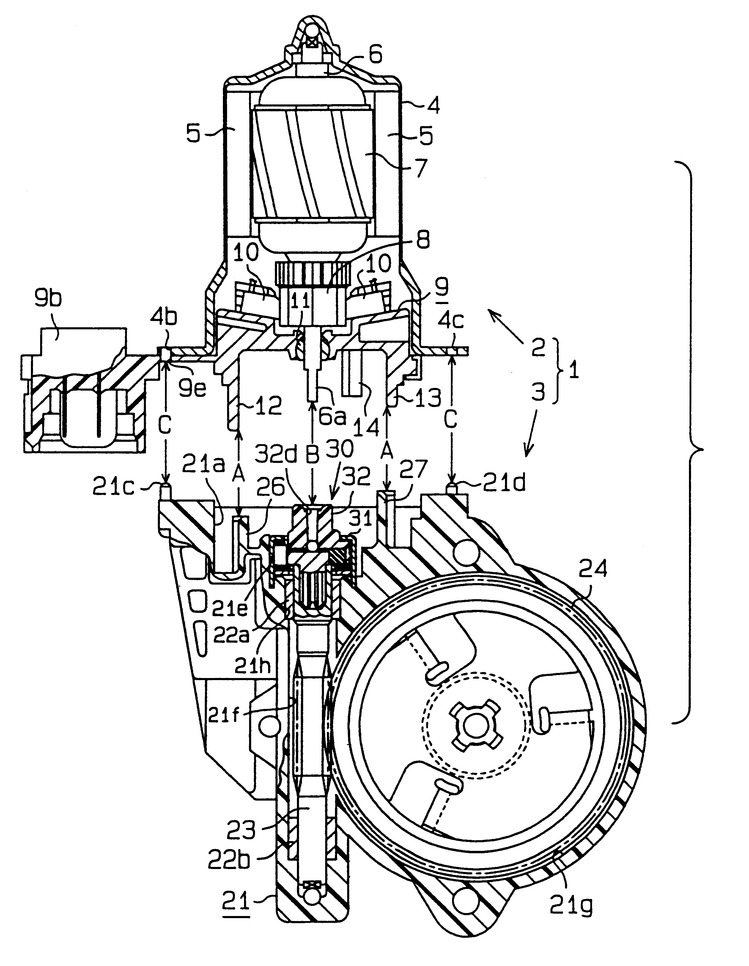
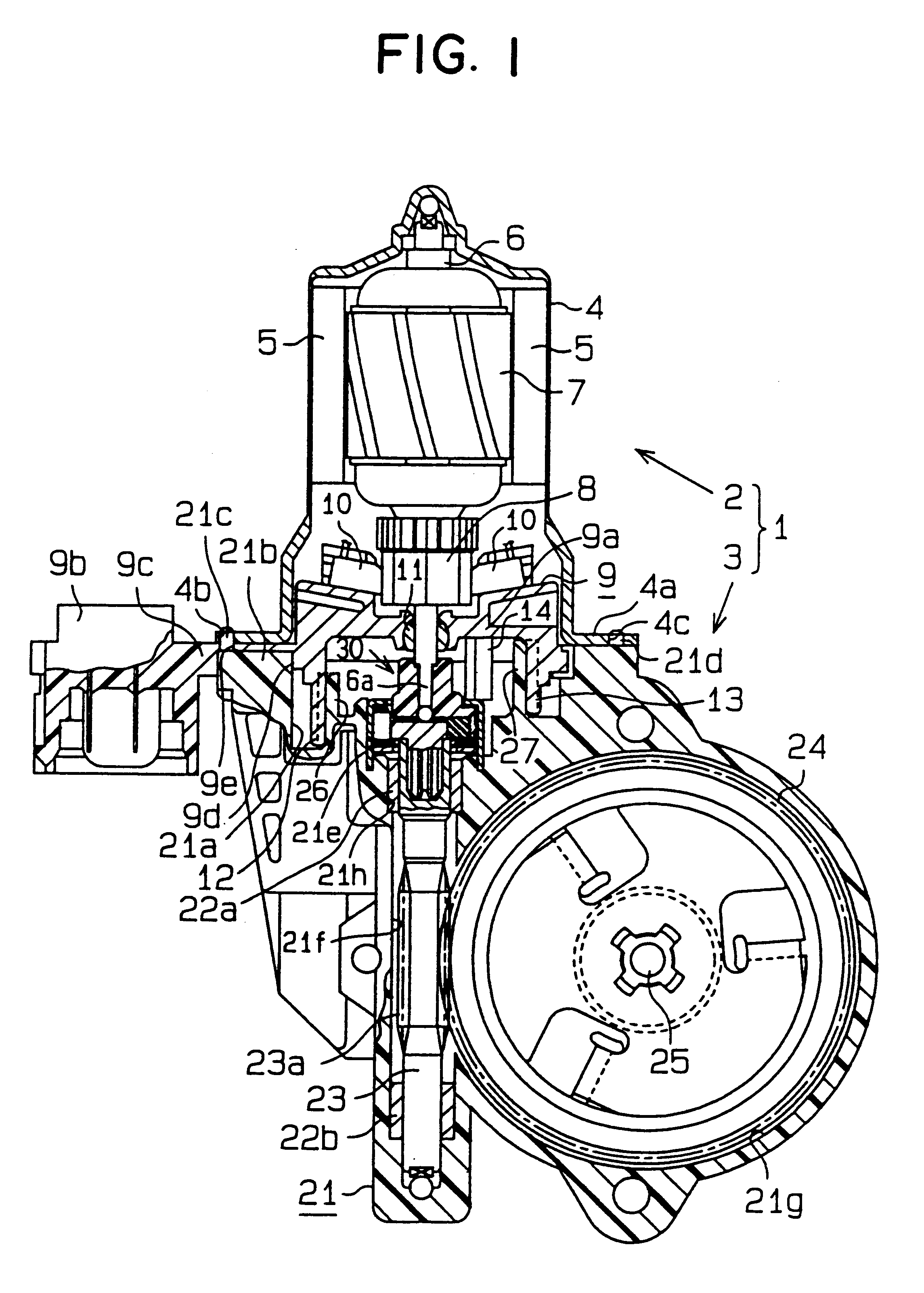
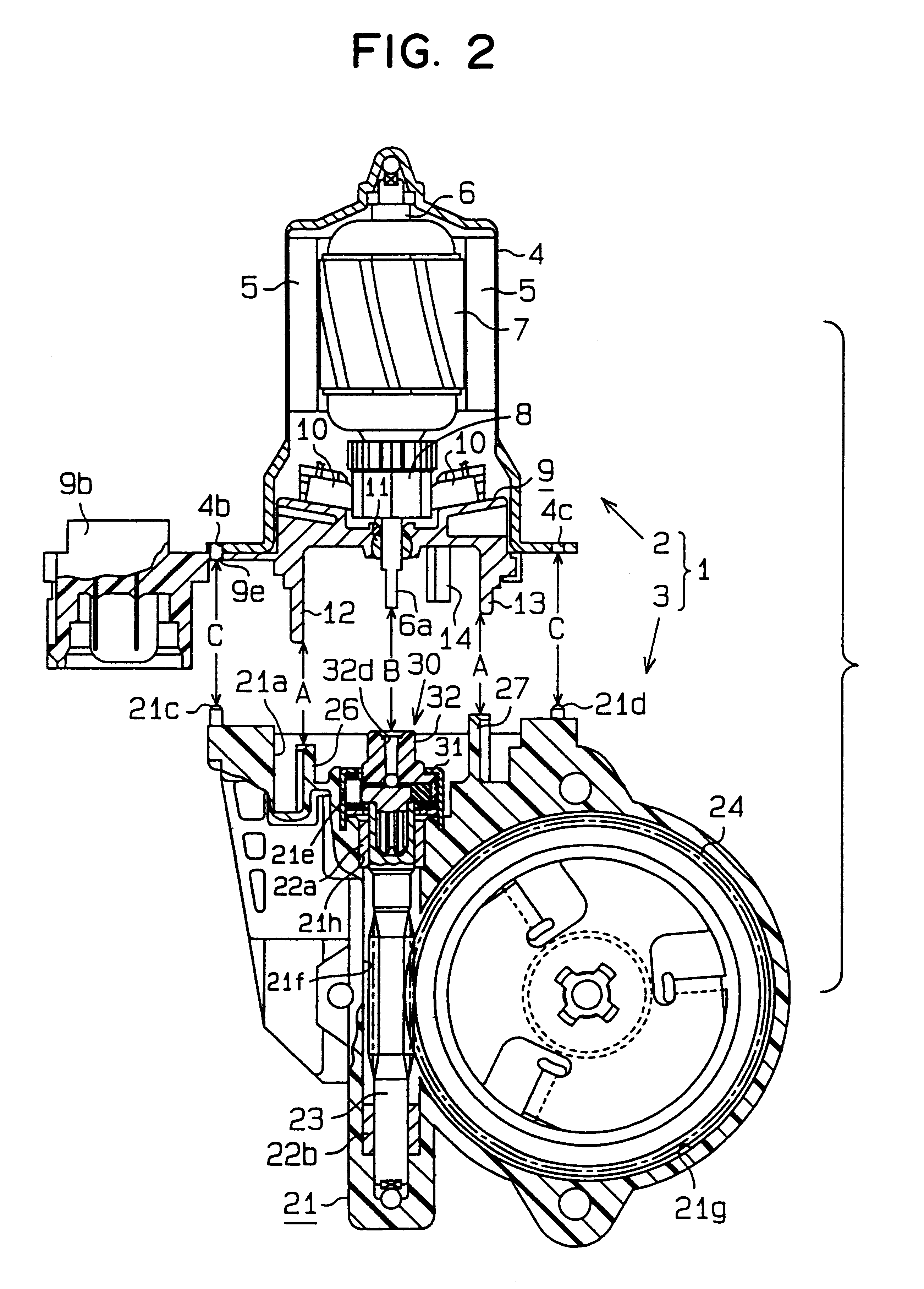
Referring now to FIGS. 1 through 10, a first embodiment of the present invention is now described. Referring to FIG. 1 and FIG. 2, a motor 1 is illustrated having a motor body 2 and a speed reducer 3. As shown in FIG. 1, the motor body 2 is equipped with a yoke housing 4, a plurality of magnets 5, a spindle 6, an armature 7, a commutator 8, a brush holder 9 made of a resin, and brushes 10.
The yoke housing 4 is formed into a generally flat bottomed cylindrical shape. On the inner circumference of the yoke housing 4, magnets 5 are fixed opposite each other. Spindle 6 is rotatably supported at a root end portion, up in FIG. 1, on the inside top of yoke housing 4. At a leading end of spindle 6, there is a two-plane bulge 6a which is chamfered parallel to the column shape, thereby acting as a first joint portion and a fitting bulge (as shown in FIG. 6).
The armature 7 is fixed at an intermediate portion of the spindle 6, thereby positioned proximate magnets 5. Commutator 8 is fixed on the...
PUM
| Property | Measurement | Unit |
|---|---|---|
| Width | aaaaa | aaaaa |
Abstract
Description
Claims
Application Information
 - Generate Ideas
- Intellectual Property
- Life Sciences
- Materials
- Tech Scout
- Unparalleled Data Quality
- Higher Quality Content
- 60% Fewer Hallucinations
Browse by: Latest US Patents, China's latest patents, Technical Efficacy Thesaurus, Application Domain, Technology Topic, Popular Technical Reports.
© 2025 PatSnap. All rights reserved.Legal|Privacy policy|Modern Slavery Act Transparency Statement|Sitemap|About US| Contact US: help@patsnap.com