Waveform translator for DC to 75 GHz oscillography

a waveform translator and oscillography technology, applied in the field of waveform translators, can solve the problems of extremely limited time resolution and accuracy of this technique, and failure to achieve the effect of sampling oscilloscopes

Inactive Publication Date: 2001-06-05
LECROY
View PDF10 Cites 38 Cited by
  • Summary
  • Abstract
  • Description
  • Claims
  • Application Information

AI Technical Summary

Problems solved by technology

Although some attempts have been made in this direction with sampling oscilloscopes, none have been successful.
The time resolution and accuracy of this technique is extremely limited by the speed and linearity of the fast ramp voltage circuit, the dynamic accuracy of the voltage comparator and the accuracy of the staircase voltage generator.
In addition, this technique is further limited by the necessity to trigger the fast ramp voltage generator in synchronization with the input waveform.
The time resolution and accuracy of this technique is extremely limited by the speed and linearity of the horizontal time ramp, and the accuracy of starting and stopping the horizontal time ramp generator.
In addition, this technique is further limited by the necessity to trigger the horizontal time ramp generator in synchronization with the input waveform.
However, the intermediate frequency requires low pass filtering to reject intermodulation products generated in the sampling process.
The phase noise of the sampler drive signal source is a significant limiting factor when measuring signals to 40 Ghz.
However, software corrections cannot always be applied e.g., when measuring eye diagrams.
The sampler drive frequency is from 10 MHz to 20 MHz, a very low frequency for accurate microwave and millimeter wave sampling above 20 GHz, and unfortunately too high a frequency to clock a high resolution analog to digital converter.
Because of the interconnect and loading, the pulse generators harmonic content can degrade.
The parasitic capacitance of two diodes introduces substantial loading on the input port.
The foregoing disadvantages contribute to limiting the disclosed inventions frequency bandwidth to 20 GHz and the dynamic range to 10 bits.
Because of the interconnect and loading, the sampling strobe synthesizer's harmonic content can degrade.
The use of a four diode bridge, a differential transistor pair, and an isolation transformer severely restricts the bandwidth of this sampler.
The time resolution and accuracy of this technique is extremely limited by the linearity of the ramp voltage generator, the dynamic accuracy of the voltage comparator, and the resolution of the digital to analog converter.
In addition, the sampling frequency is limited by the speed of the discrete time signal processor and results in a maximum sampling frequency of 25 KHz, a very low frequency for accurate microwave and millimeter wave sampling above 2 GHz.
Furthermore, increasing the sampling frequency would preclude the use of a high resolution analog to digital converter.
The inability to measure signals beyond 1 GHz is a severe disadvantage of this prior art.
The use of a four diode bridge and an isolation transformer severely restricts the bandwidth of this sampler.
In addition, the inherent low frequency performance of the impulse generator, being remote from the sampling bridge, will limit the upper frequency range of the sampling apparatus.
The impedance match at the input port of this apparatus is problematic due to the coaxial to waveguide transition into the guide and by the parasitic loading of two diodes in the sampler circuit.
In addition, waveguide dispersion of the sampler drive pulse can lead to taking multiple samples of the input waveform per sampler drive period.
The disclosed circuit requires a substantial amount of power making it impractical to use in a sampling oscilloscope.
In addition, the input repetition rate is limited to a fairly narrow range of low frequencies.

Method used


Image

  • Waveform translator for DC to 75 GHz oscillography
  • Waveform translator for DC to 75 GHz oscillography
  • Waveform translator for DC to 75 GHz oscillography

Examples


Embodiment Construction

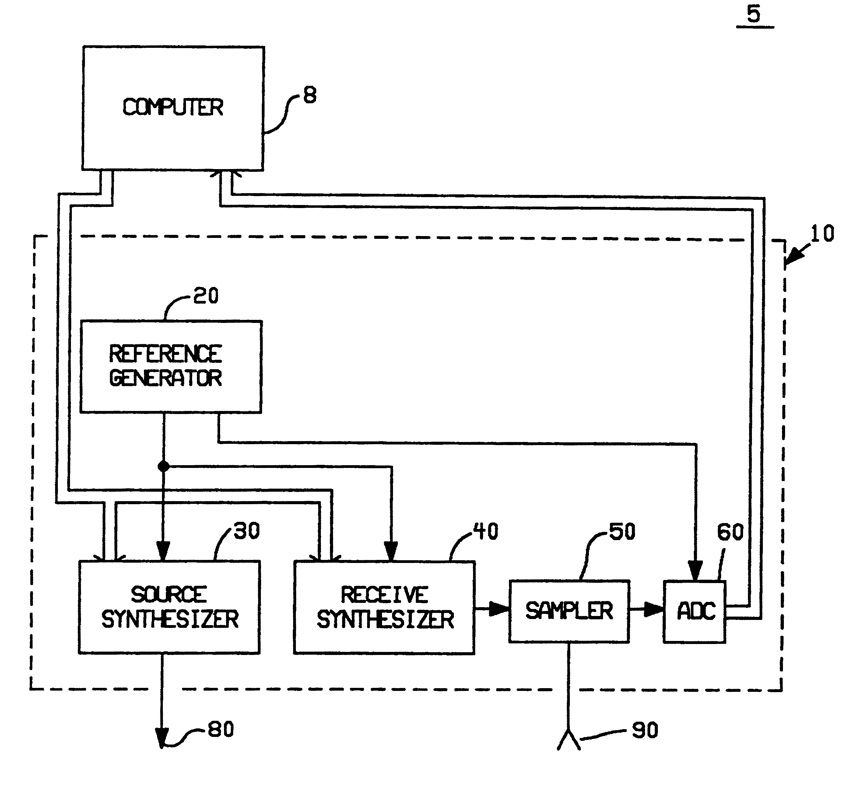
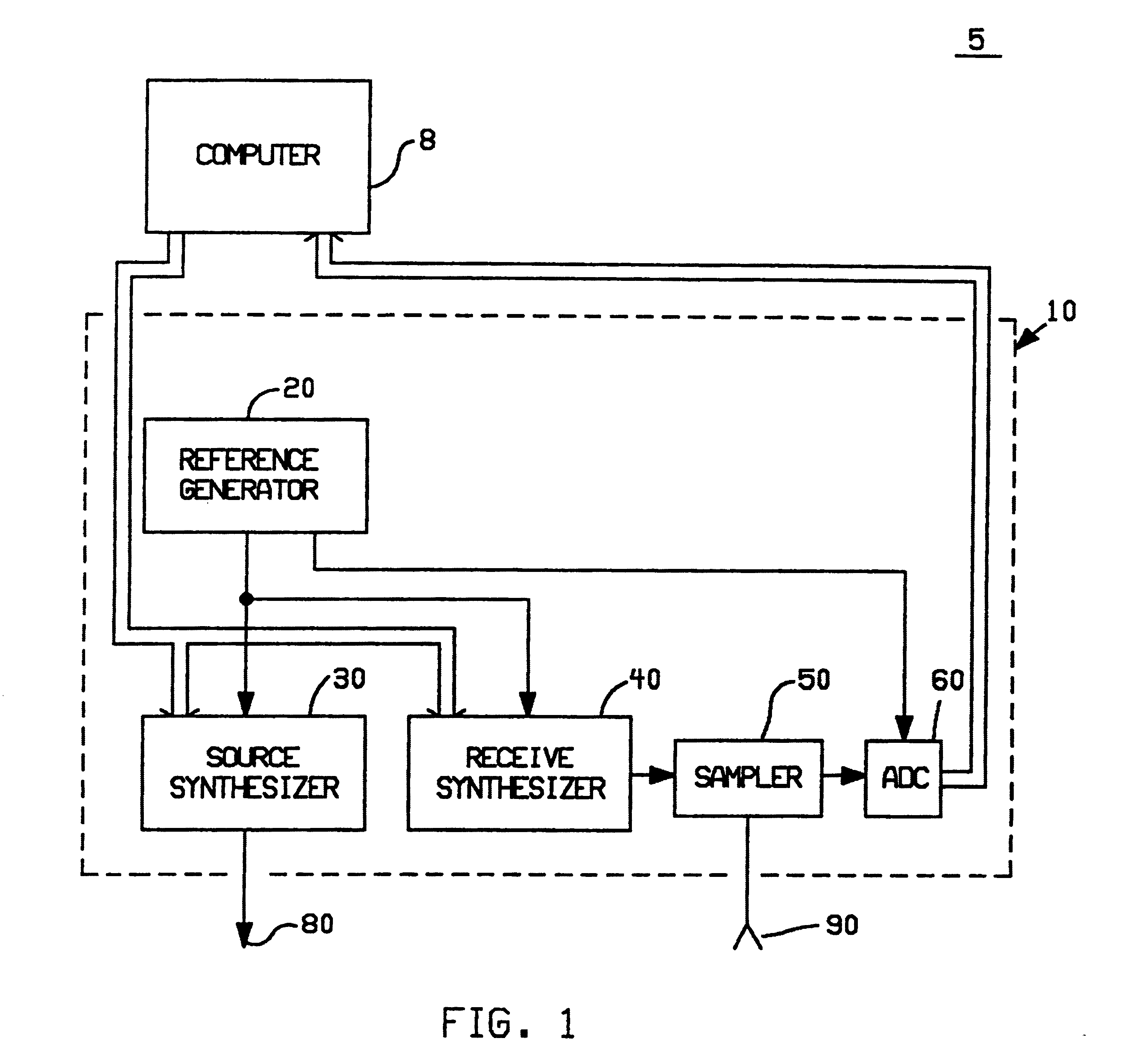
As shown in FIG. 1, one embodiment of the present invention provides a waveform translator generally indicated by numeral 10. The waveform translator is preferably incorporated into a test instrument for DC to 75 GHz oscillography generally indicated by numeral 5 comprising a waveform translator in accordance with the present invention, and a computer numeral 8.

As shown in FIG. 1, the waveform translator comprises a reference generator 20 to provide a reference signal for a source synthesizer 30 and a receive synthesizer 40, and to provide a clock signal for a ADC 60. The source synthesizer 30 drives an output test signal 80, the receive synthesizer 40 drives the control port on a sampler 50. Preferably, a computer 8 programs the source synthesizer and the receive synthesizer. An input signal 90 is received by the sampler 50, the samplers output signal is digitized in ADC 60. Preferably the digitized waveform is fed to the computer 8 to process the digitized waveform and display the...


PUM


Abstract

A waveform translator in which the frequency spectrum of a repetitive non band limited input signal is translated to an equivalent frequency spectrum which is harmonically related to a fixed reference frequency. In the waveform translator a synthesized source generator and a synthesized receive generator are made coherent. The source generator drives a DUT, and the receive generator coupled to a sampler, samples the DUT to produce a non band limited difference signal harmonically related to the fixed reference frequency. The difference signal is digitized in an analog to digital converter which is clocked at the reference frequency and produces a predetermined integer number of data points per cycle corresponding to the input signal. A computer is coupled to the waveform translator for DC to 75 GHz oscillography.

Description

BACKGROUND--FIELD OF INVENTIONThis invention relates to test and measurement equipment. Specifically the invention is directed toward a waveform translator, i.e., translating the frequency spectrum of a repetitive non band limited input signal, to an equivalent frequency spectrum which is harmonically related to a fixed reference frequency. An analog to digital converter is clocked at the reference frequency to produce a digitized waveform with a predetermined integer number of data points per cycle corresponding to the input signal.BACKGROUND--DESCRIPTION OF PRIOR ARTThere was a long felt and unsolved need to display time domain waveforms from DC through the millimeter wave range. Although some attempts have been made in this direction with sampling oscilloscopes, none have been successful. The reason for this is that recent attempts have tried to leverage off existing technology, and new technology is required for the vertical sampler section and the horizontal timing section.In a...

Claims


Application Information

Patent Timeline
Patent Type & Authority Patents(United States)
IPC IPC(8): G01R13/34G01R13/22G01R23/02G01R19/25G01R23/00
CPCG01R13/345G01R19/2509G01R23/02
Inventor MILLER, ROBERT
Owner LECROY
Why Eureka
Try Eureka