

Iterative filter framework for medical images
Inactive Publication Date: 2001-06-12
GENERAL ELECTRIC CO
View PDF24 Cites 51 Cited by
- Summary
- Abstract
- Description
- Claims
- Application Information
AI Technical Summary
Benefits of technology
if (alpha_f+beta_f)>1, grey scale compression occurs to provide an overall smoothing effect.
Weak edge region: As a rule of thumb, weak edge regions must be attenuated. Sharpening the weak edge regions in general increases the chance of noise amplification and the appearance of "worms" in MR images. The texture in these regions must be maintained to have natural appearance in order to avoid "smudging" and "smushing" of pixel intensities.
Problems solved by technology
Unfortunately, this solution results in an increased scan time that inconveniences the patient and is expensive.
These measures drive up the cost of the equipment, and in the case of x-ray, increase the dose of ionizing radiation to the patient.
However, injected contrast agents only improve a limited range of image characteristics, and because it is as an invasive technique, it is sometimes inappropriate for medical reasons.
However, histogram modifications which expand the dynamic range of the data, also increase the noise in the image.
Local histogram modifications cause a blocking effect that results in a lack of uniformity over the entire image.
However, global filtering techniques tend to blur the images and eliminate the lower frequency regions.
This makes clinical evaluation of the images difficult.
However, the local filtering techniques have difficulty distinguishing between sudden image variations attributable to edges and sudden image variations attributable to noise.
These techniques also fail to account for differences in edge direction and regional variance, producing an image which is overly smooth without consideration of the edges.
Complicated acquisition processes, such as MRI imaging are too difficult to model accurately, and the parameters of a complicated model for a given image can require lengthy iterative computations.
Such analysis is computationally intensive, time consuming, and prone to errors.
Method used
View moreImage
Smart ImageViewing Examples

Examples
example filter 3
Short description: High smooth and very little sharpen.
Detailed description: Overall this filter produces smoothing and very little sharpening to suppress noise and provides smoother structural edges.
Suggested usage: High resolution, low signal images.
Parameter Combination
Login to View More PUM
 Abstract
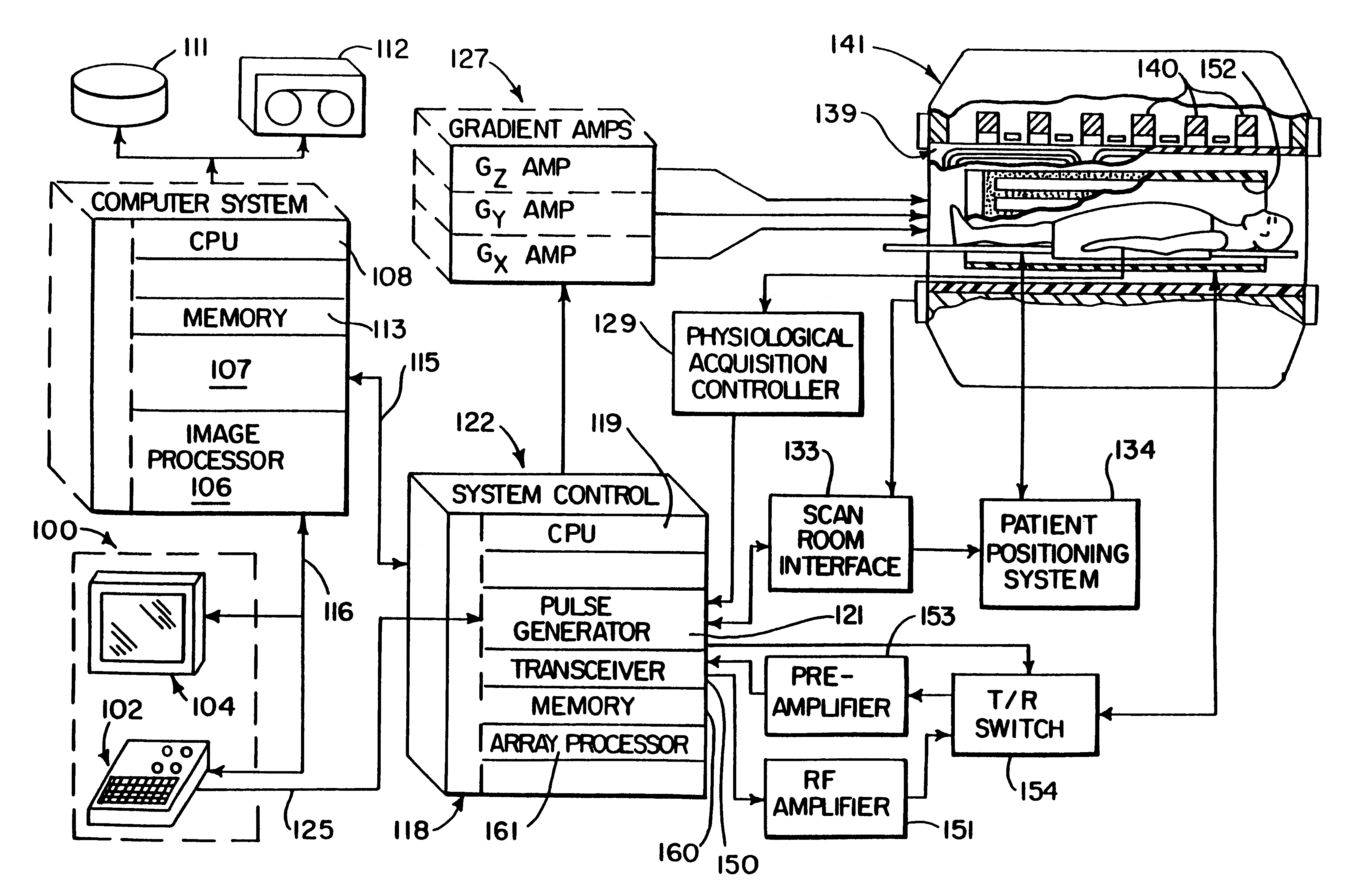
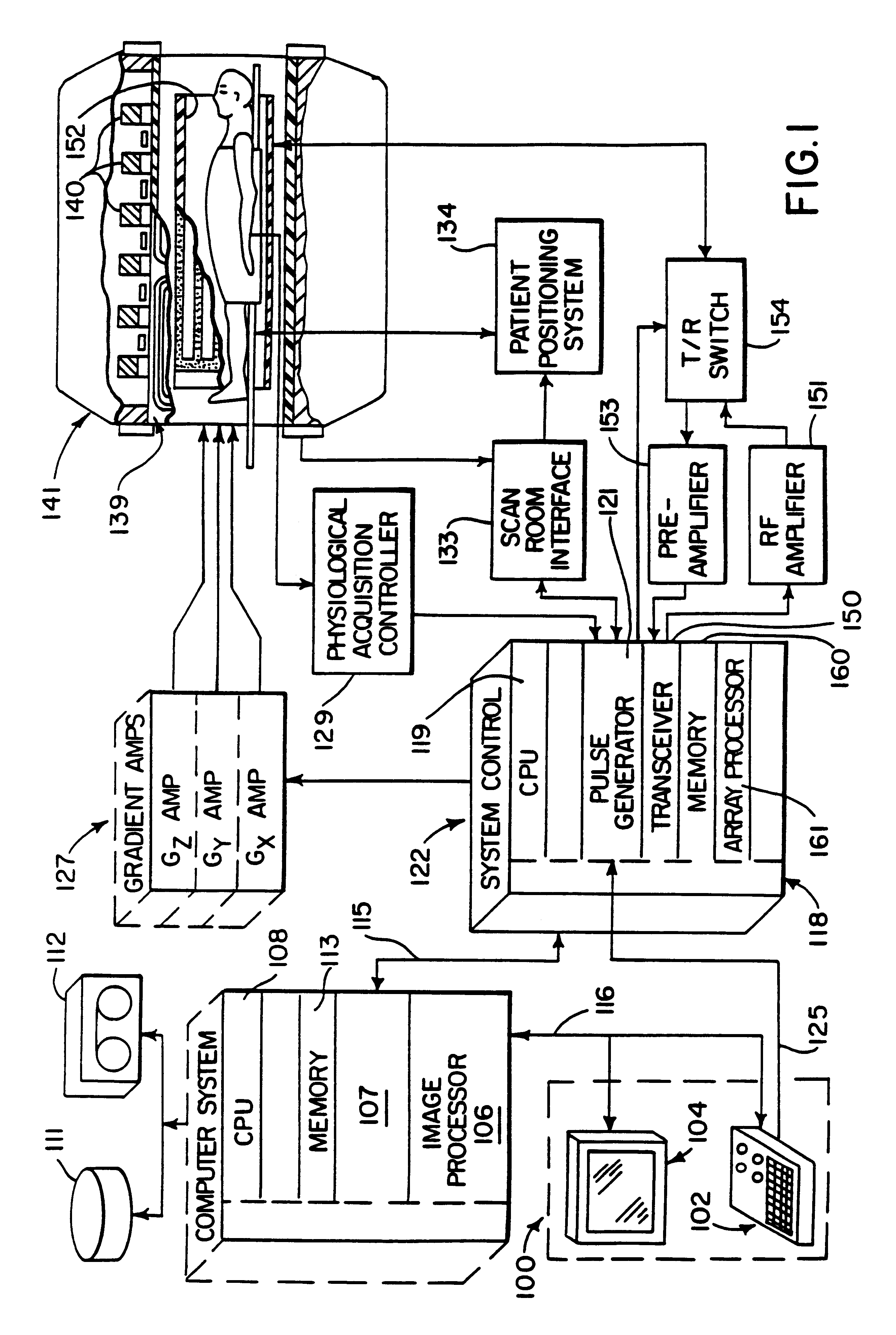
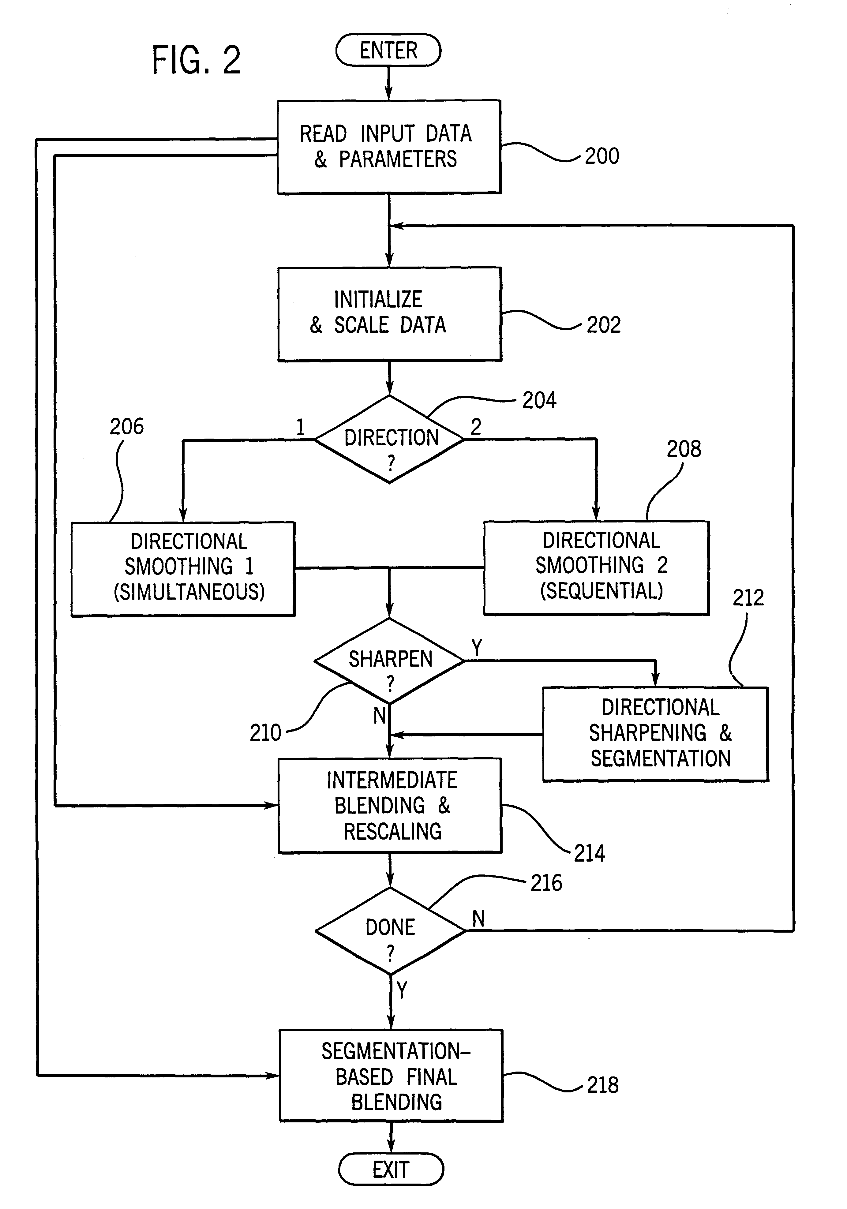
Functional filter elements are linked in a multi-pass filter framework that forms part of an MRI system. The filter framework is configured by a set of parameters selected by the operator to perform smoothing and edge sharpening functions on acquired MR images. The functional filter elements used during each pass through the filter framework and the number of passes through it are configurable to obtain a wide variety of visual effects on medical images.
Description
The field of the invention is medical imaging, and particularly, the filtering and enhancement of medical images to improve their visual quality.The quality of medical images is a function of the imaging modality used and the particular method used to acquire the image data. As a general matter, regardless of the imaging modality used, the quality of medical images can be improved by acquiring redundant data which can be averaged to reduce the effects of random noise. Unfortunately, this solution results in an increased scan time that inconveniences the patient and is expensive. Another approach is to increase the power of the imaging system. In MRI this may take the form of a stronger polarizing field (e.g. 1.5 Tesla instead of 0.5 Tesla), in x-ray systems this can take the form of a higher power x-ray beam, and in ultrasound this may take the form of a more powerful rf amplifier and transducer. These measures drive up the cost of the equipment, and in the case of x-ray, increase t...
Claims
Login to View More Application Information
Patent Timeline
 IPC IPC(8): G06T5/00A61B5/055G01R33/54G06T1/00G06T1/20G06T5/20G06T7/00
CPCG06T1/20G06T5/20
InventorAVINASH, GOPAL B.
OwnerGENERAL ELECTRIC CO