

Blow-by gas passage abnormality detecting system for internal combustion engines
a technology of abnormality detection and blow-by gas, which is applied in the direction of machines/engines, electrical control, mechanical equipment, etc., can solve the problems of blow-by gas being released, contrary to the desired prevention of environmental pollution
- Summary
- Abstract
- Description
- Claims
- Application Information
AI Technical Summary
Benefits of technology
Problems solved by technology
Method used
Image

Examples
first embodiment
Step S105, that is a procedure for processing after an abnormality decision in the ECU 40 used in the blow-by gas passage abnormality detecting system of an internal combustion engine is shown in FIG. 4. Here, when it is decided that the blow-by gas passage 27 has the abnormality (i.e., the leakage or the disengagement), the reliabilities in the various detection steps and the control steps, as follows, cannot be kept so that these steps are inhibited.
In FIG. 4, at first step S201, the trouble detection of the air flow meter 33 for detecting the intake flow in the intake passage 12 is inhibited; at next step S202, the trouble detection of the ISC valve 20 is inhibited; at next step S203, the trouble detection of the ISC system; at next step S204, the trouble detection of an EGR (Exhaust Gas Recirculation) system (although not shown in FIG. 1) is inhibited; and at next step S205, the trouble detection of the fuel system (such as a fuel injection time control system) is inhibited.
The...
embodiment 2
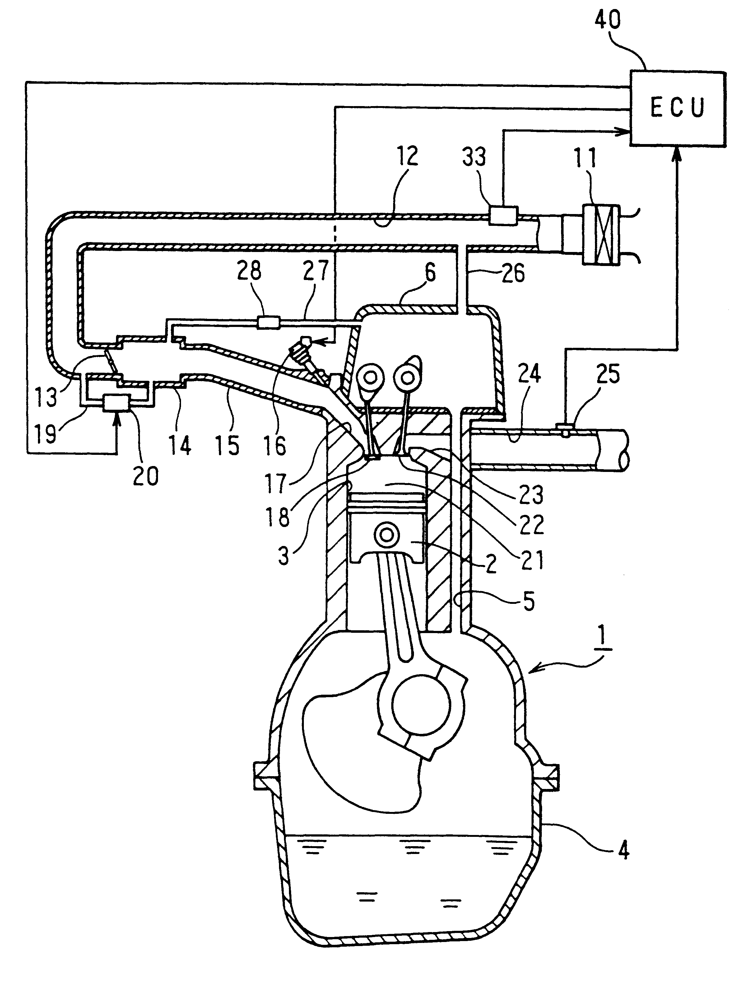
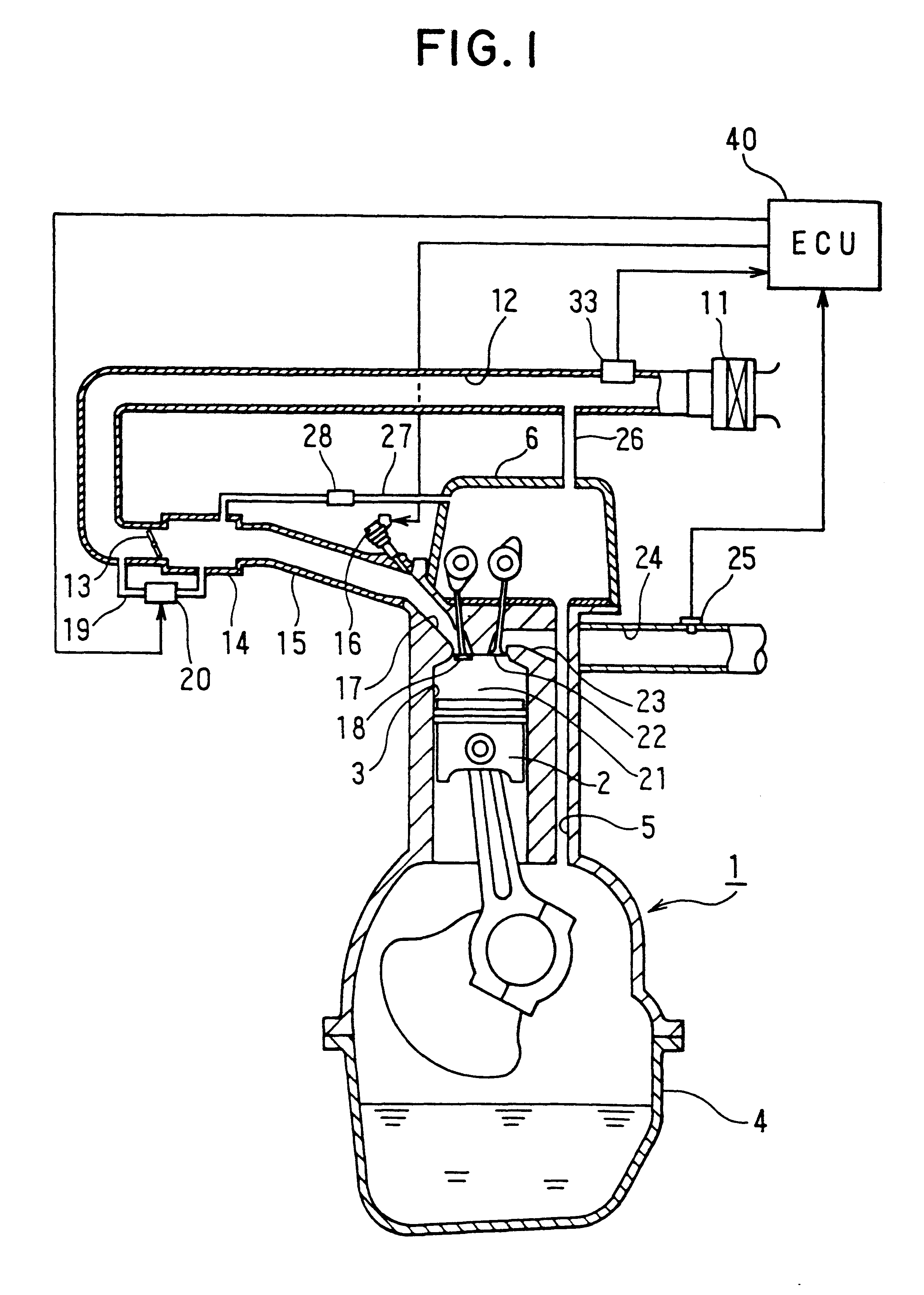
In the second embodiment shown in FIG. 5, the entire construction of the blow-by gas passage abnormality detecting system for an internal combustion engine according to the present embodiment is identical to that of the schematic diagram of FIG. 1 in the aforementioned first embodiment.
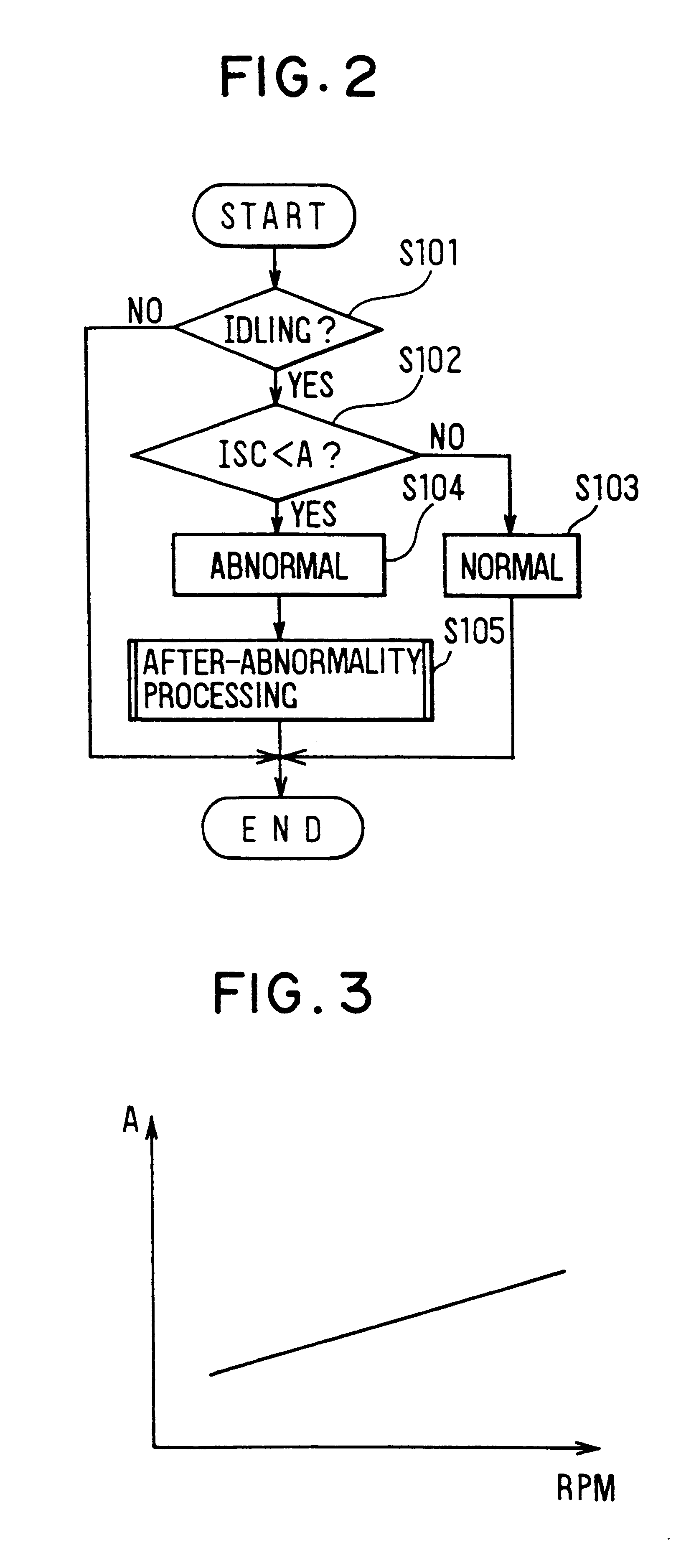
In FIG. 5, at step S301, it is decided whether or not the running state of the internal combustion engine 1 is idle. When the decision of step S301 is NO indicating that the running state is other than the idle time, the present routine is ended without any operation. On the other hand, when the decision of step S301 is YES, that is, when the throttle opening of the throttle valve 13 is less than a predetermined value to indicate that the running state is idle, the routine advances to step S302, at which it is decided whether or not the prevailing A / F (air / fuel ratio) F / B (feedback) amount on the basis of the output coming from the oxygen concentration sensor 25 are more than a decision value B. This ...
embodiment 3
In the third embodiment shown in FIG. 7, the entire construction of the blow-by gas passage abnormality detecting system for an internal combustion engine according to the present embodiment is modified from the schematic diagram of FIG. 1 of the first embodiment by arranging additionally an intake pressure sensor for detecting the intake pressure in the surge tank leading from the intake passage 12.
In FIG. 7, at step S401, it is decided whether or not the running state of the internal combustion engine 1 is idle. When the decision of step S401 is NO indicating that the running state is other than the idle time, the present routine is ended without any operation. On the other hand, when the decision of step S401 is YES, that is, when the throttle opening of the throttle valve 13 is less than a predetermined value to indicate that the running state is idle, the routine advances to step S402, at which it is decided whether or not the prevailing intake pressure detected by the intake p...
PUM
 Abstract
Description
Claims
Application Information