
Apparatus for establishing branch wells from a parent well

a technology for branch wells and parent wells, applied in the field of wells, can solve problems such as inability to provide and difficulty in sealing

Inactive Publication Date: 2001-06-19
SCHLUMBERGER TECH CORP
View PDF62 Cites 54 Cited by
  • Summary
  • Abstract
  • Description
  • Claims
  • Application Information

AI Technical Summary

Benefits of technology

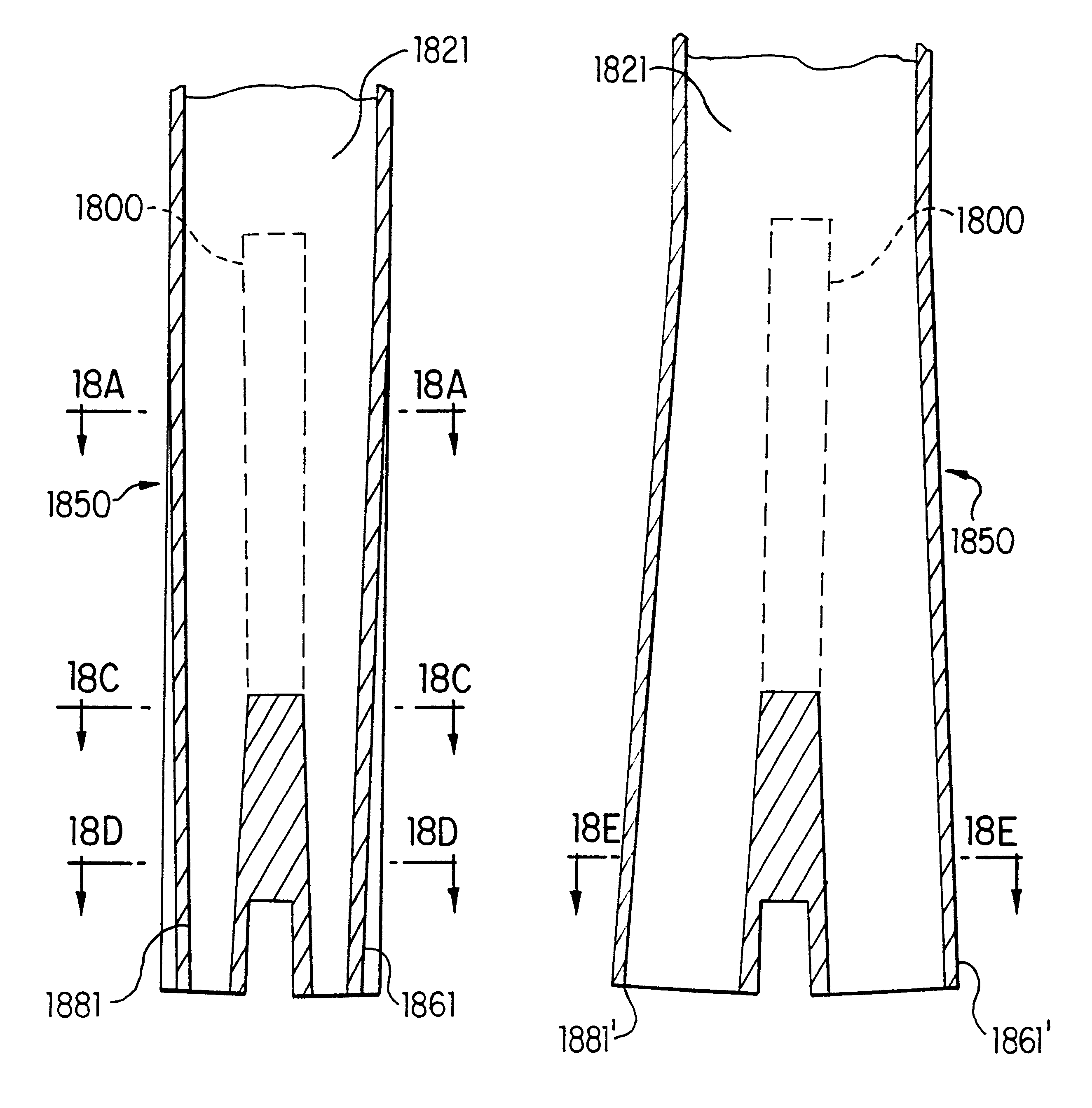
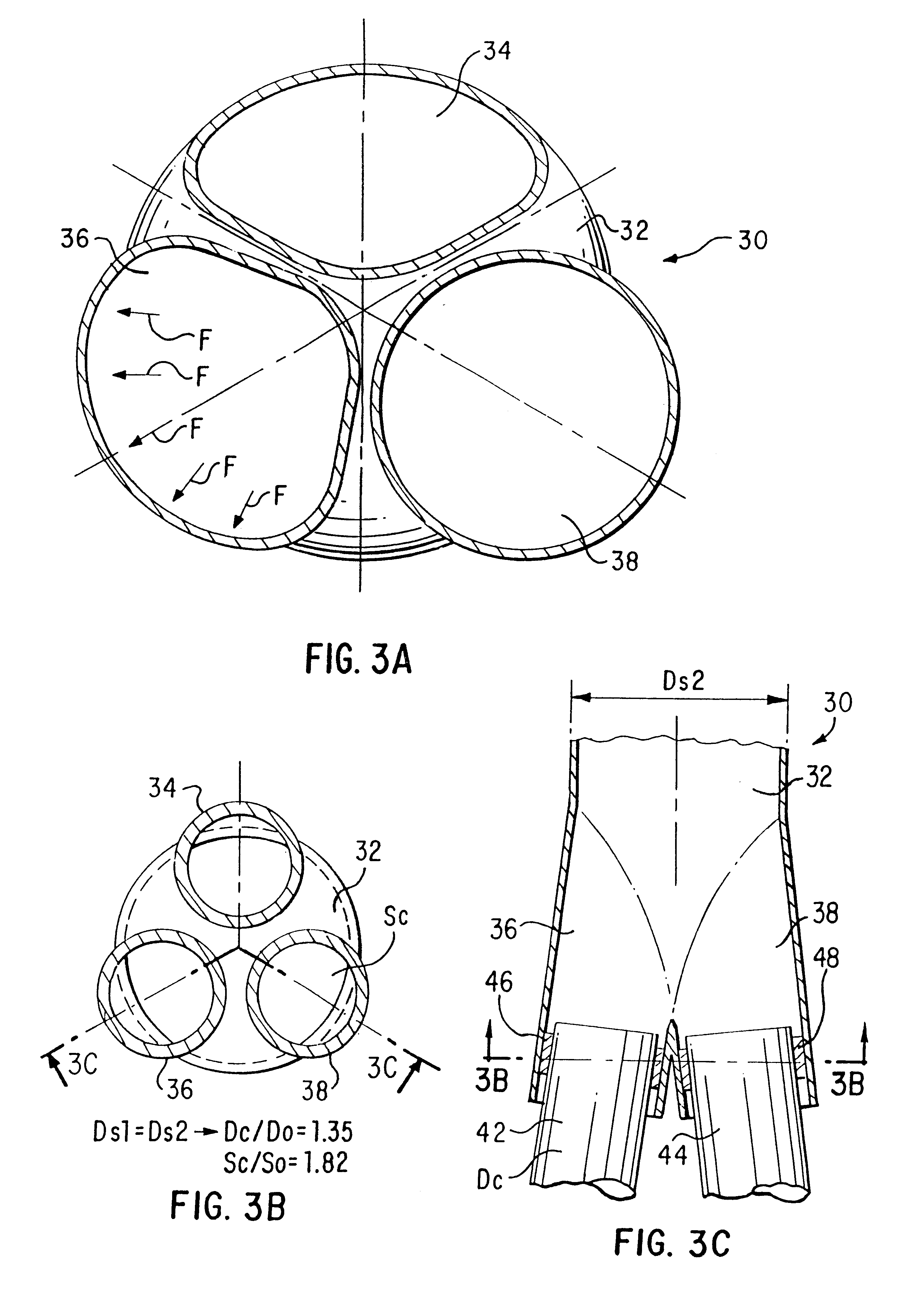
Multiple branching outlet members, each of which is integrally connected to the second end of the branching chamber, provide fluid communication with the branching chamber. Each of the outlet members is prefabricated such that such members are in a retracted position for insertion of the sub into and down through the parent well to a deployment location deep in the well. Each of the multiple outlets is substantially totally within an imaginary cylinder which is coaxial with and of substantially the same radius as the first end of the branching chamber. The prefabrication of the outlet members causes each outlet member to be transformed in cross-sectional shape from a round or circular shape to an oblong or other suitable shape such that its outer profile fits within the imaginary cylinder. The outer profile of each outlet member cooperates with the outer profiles of other outlet members to substantially fill the area of a cross-section of the imaginary cylinder. As a result, a substantially greater cross-sectional area of the multiple outlet members is achieved within a cross-section of the imaginary cylinder as compared with a corresponding number of tubular multiple outlet members of circular cross-section.
According to a second, alternative embodiment of the invention, a branching sub is provided which allows multiple branches from a parent casing without the need for sealing joints and which allows the use of conventional well controlled liner packers and casing joints. The geometry of the housing of the branching sub allows the housing to achieve maximum pressure rating considering the size of the branch outlet with regard to the size of the parent casing.

Problems solved by technology

Furthermore, difficult sealing problems have faced the art for establishing communication between the branch well and the primary well.
Such sealing problems relate to the requirement of ensuring the connectivity of the branch casing liner with the parent casing and to maintaining hydraulic isolation of the juncture under differential pressure.
A fundamental problem exists in establishing branch wells at a depth in a primary well in that apparatus for establishing such branch wells must be run on parent casing which must fit within intermediate casing of the well.
In man y cases, especially where the conductor pipe must be deployed at a depth in the well, rather than at the surface of the well, it is not feasible to provide a borehole of sufficient outer diameter to allow branch well outlets of sufficient diameter to be installed.

Method used


Image

  • Apparatus for establishing branch wells from a parent well
  • Apparatus for establishing branch wells from a parent well
  • Apparatus for establishing branch wells from a parent well

Examples


experiment phase 1

Two casing sizes were selected: a first one, one meter long was 7 inch diameter casing with a wall thickness of 4.5 mm; the second was one meter long and was 7 inch diameter casing with a wall thickness of 8 mm. A hydraulic jack was designed for placement in a casing for expanding it. Each casing was successfully preformed into an elliptical shape, e.g., to simulate the shape of outlet member 34 in FIG. 3A and reformed into circular shape while using a circularizing forming head with the jack. Circularity, like that of outlet member 38 of FIG. 3A was achieved with plus or minus difference from perfect circularity of 2 mm.

experiment phase 2

Two, one meter long, 7 inch diameter, 23 pound casings were machined axially at an angle of 2.5 degrees. The two casings were joined together at their machined surfaces by electron beam (EB) welding. The joined casings were deformed to fit inside an 11 inch diameter. The welding at the junction of the two casings and the casings themselves had no visible cracks. The maximum diameter was 10.7 inches; the minimum diameter was 10.5 inches.

a) Machinery

Before milling each casing at an angle of 2.5 degrees, a spacer was temporarily welded at its end to avoid possible deformation during machining. Next each casing was machined roughly and then finished to assure that each machined surface was coplanar with the other. The spacer welded at the end of the casing was machined at the same time.

b) Welding

The two machined casings were assembled together with a jig, pressed together and carefully positioned to maintain alignment of the machined surfaces. The assembly was then fixed by several tung...

experiment phase 3

A fill length prototype with two 7 inch casings connected to a 9 5 / 8 inch casing was manufactured and pressure tested. Testing stopped at 27 bar because deformation was occurring without pressure variation.

a) Machining

Machining was performed in the same way as for the two previous junctions except that the length of the casings was 1.25 meters instead of 1 meter, and a groove was machined around the elliptical profile to enhance the EB welding process. Additionally, a blind hole was machined on the plane of the cut of each casing to install a pin between the two casings to provide better positioning. The upper adapter was machined out of a solid bar of steel on a numerically controlled milling machine to-provide a continuous profile between the 7 inch casings, with a 2.5 degree angle, and the 9 5 / 8 inch casing. The adapter was machined to accept a plug. The inner diameter of the lower end of the 7 inch casings was machined to accept the expanding plugs.

b) Welding

The two machined cas...


PUM


Abstract

A method and apparatus for creating multiple branch wells from a parent well is disclosed. According to a first embodiment of the invention a multiple branching sub is provided for placement at a branching node of a well. Such sub includes a branching chamber and a plurality of branching outlet members. The outlet members, during construction of the branching sub, have previously been distorted into oblong shapes so that all of the branching outlet members fit within an imaginary cylinder which is coaxial with and substantially the same radius as the branching chamber. According to one embodiment, the distorted outlet members are characterized by an outer convex shape. In another embodiment, the distorted outlet members are characterized by an outer concave shape when in a retracted state. After deployment of the branching sub via a parent casing in the well, a forming tool is lowered to the interior of the sub. The outlet members are extended outwardly by the forming tool and simultaneously formed into substantially round tubes. Next, each outlet member is plugged with cement, after which each branch well is drilled through a respective outlet member. If desired, each branch may be lined with casing and sealed to a branching outlet by means of a casing hanger. A manifold placed in the branching chamber controls the production of each branch well to the parent well. According to a second embodiment of the invention, a pressure resistant branching sub is provided which may be installed in series with a casing string, and the associated equipment used for the installation operation and intervention of a well. The branching sub includes a main pipe and a lateral outlet.

Description

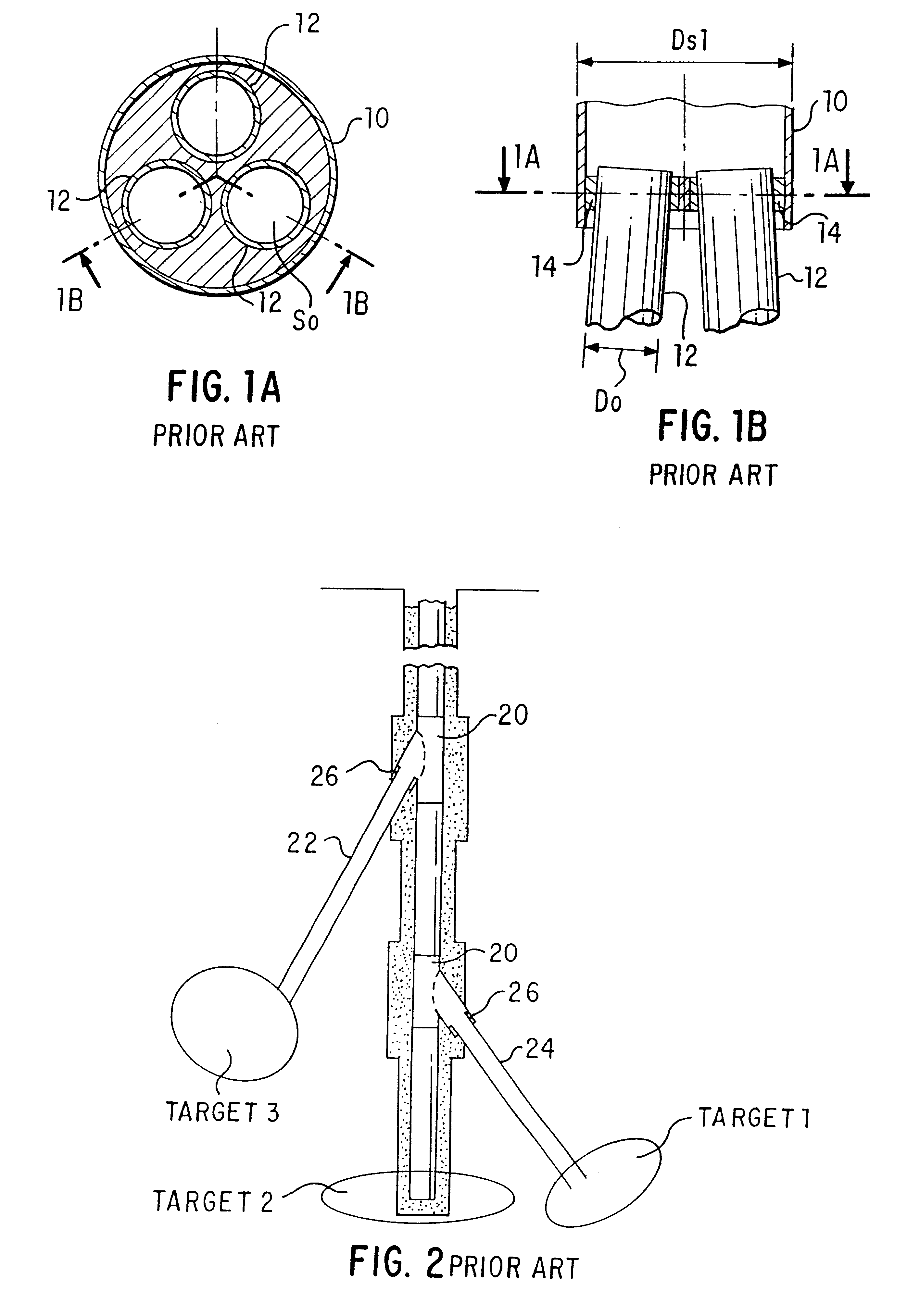
1. Field of the InventionThis invention relates generally to the field of wells, particularly to the field of establishing branch wells from a parent hydrocarbon well. More particularly the invention relates to establishing multiple branch wells from a common depth point, called a node, deep in the well.2. Description of the Related ArtMultiple wells have been drilled from a common location, particularly while drilling from an offshore platform where multiple wells must be drilled to cover the great expenses of offshore drilling. As illustrated in Figures 1A and 1B, such wells are drilled through a common conductor pipe, and each well includes surface casing liners, intermediate casing and parent casing as is well known in the field of offshore drilling of hydrocarbon wells. U.S. Pat. No. 5,458,199 describes apparatus and methods for drilling multiple wells from a common wellbore at or near the surface of the earth. U.S. Pat. No. 4,573,541 describes a downhole take-off assembly for ...

Claims


Application Information

Patent Timeline
Patent Type & Authority Patents(United States)
IPC IPC(8): E21B7/04E21B7/06E21B41/00E21B43/10E21B43/02E21B7/08
CPCE21B7/061E21B41/0042E21B43/105
Inventor OHMER, HERVE
Owner SCHLUMBERGER TECH CORP
Learn More