Integrated circuit with both clamp protection and high impedance protection from input overshoot

a technology of integrated circuits and clamps, applied in the direction of logic circuit coupling/interface arrangement, pulse generators, pulse techniques, etc., can solve the problems of leakage current, leakage current, over the system bus, and the supply voltage employed by ics also has decreased

Inactive Publication Date: 2001-07-03
ALTERA CORP
View PDF70 Cites 31 Cited by
  • Summary
  • Abstract
  • Description
  • Claims
  • Application Information

AI Technical Summary

Problems solved by technology

However, as the dimensions of the circuits in ICs have decreased, the supply voltages employed by ICs also have decreased.
A problem with mixed signal systems has been the occurrence of leakage currents, over the system bus, from an IC operating at a higher supply voltage to an IC operating at a lower supply voltage.
Thus, leakage current may result when an output level high signal is imparted from one IC onto an I/O pin of another IC operating at a lower supply voltage.
However, the driver circuit shown in FIG. 1 is not tolerant to high voltages, and may not be useful in the case where input voltages are imparted by an integrated circuit having a supply voltage above a level of the first supply voltage 117.
This poses potential problems.
If VCC rises above maximum allowable levels and remains at those levels for longer than an acceptable time, the device may have oxide reliability issues.
Unfortunately, as explained above, the performance requirements of these different systems often may be at odds with each other.
Also, it is not possible to configure one I/O pin to comply with a PCI system requirements and to configure another I/O pin to comply with a mixed signal tolerant system.
Moreover, the actual process of con

Method used


Image

  • Integrated circuit with both clamp protection and high impedance protection from input overshoot
  • Integrated circuit with both clamp protection and high impedance protection from input overshoot
  • Integrated circuit with both clamp protection and high impedance protection from input overshoot

Examples


Embodiment Construction

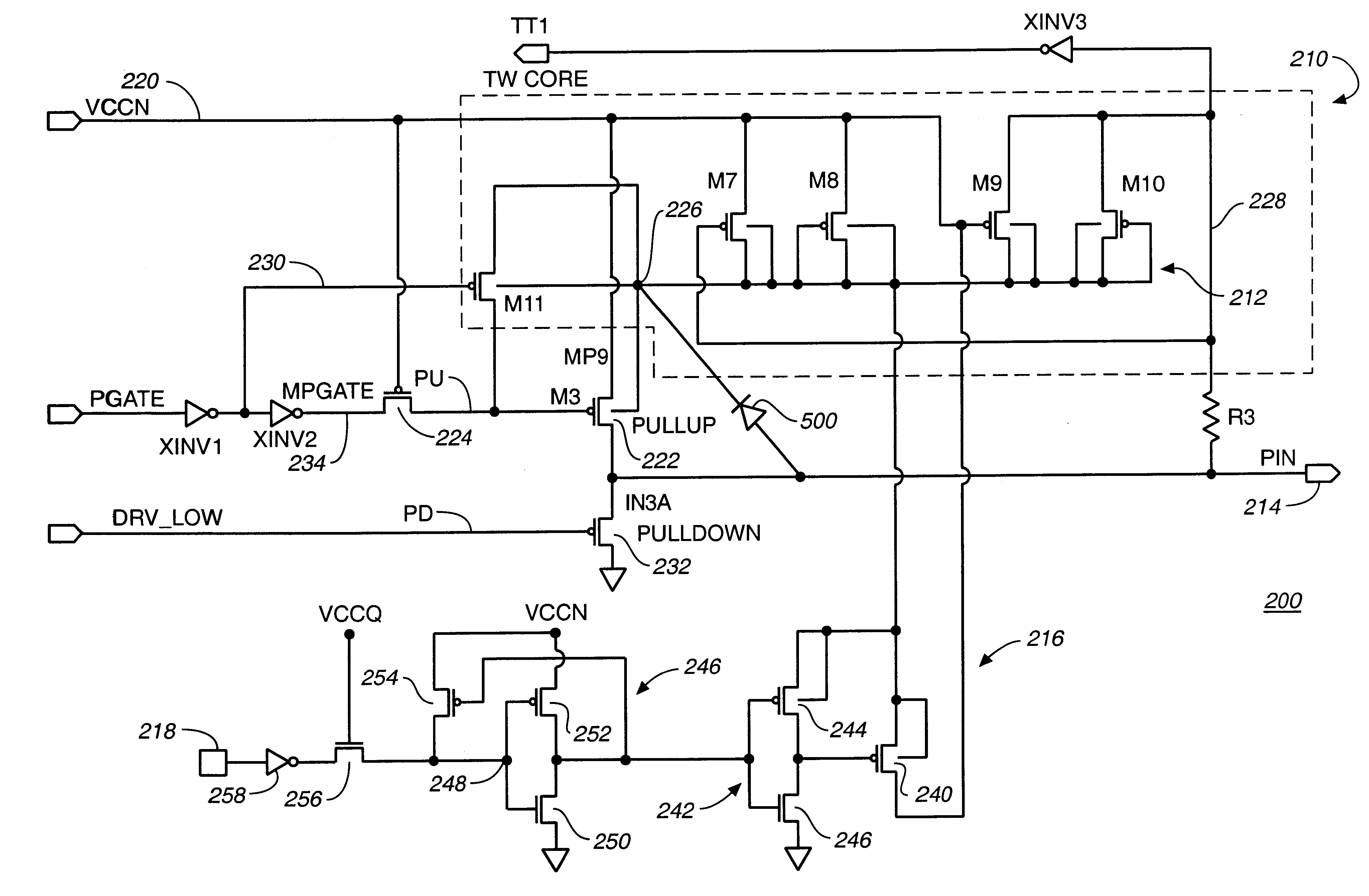
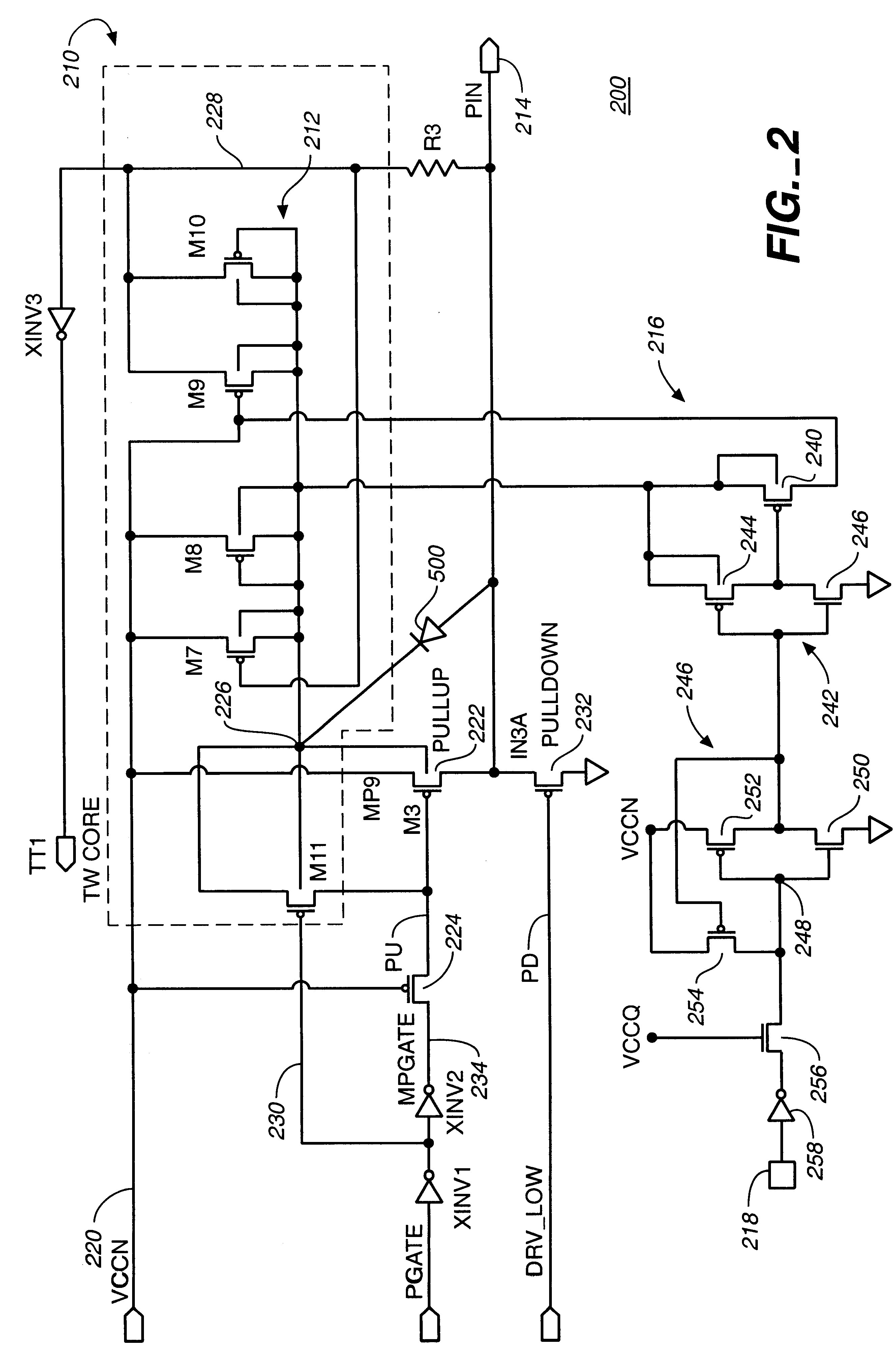
FIG. 3 is a diagram of a first alternative embodiment of the high-voltage tolerant I / O circuit 300 in accordance with the present invention. In FIG. 3, a voltage bias generator 212' is similar to voltage bias generator 212 of FIG. 2. Only the differences between voltage bias generator 212' and voltage bias generator 212 will be discussed. Components in FIG. 3 that are substantially the same as corresponding components in FIG. 2 are labeled with primed reference numbers. The current sink-voltage clamp overvoltage protection circuitry are identical in FIGS. 2 and 3.

Voltage bias generator 212' has a bias output node 226' which is coupled to the n-well of pull-up driver 222'. Transistors M7, M8, M9, and M10 are configured and operate similarly as the similarly labeled transistors in voltage bias generator 212'. These transistors generate the voltage at n-well voltage bias generator output node 226'.

A voltage at PU is generated by transistors M17, M19, and M11A, in contrast to a single t...


PUM


Abstract

An integrated circuit is provided for use with a supply voltage and which includes an input/output (I/O) circuit with an output driver with a pull-up transistor and a pull-down transistor and which includes an I/O pin connected to receive output signals from the output driver and connected to provide input signals to the integrated circuit, the protection circuit comprising: bias circuitry that imparts a bias voltage to the pull-up transistor so as to substantially prevent leakage current when a voltage applied externally to the I/O pin rises above the supply voltage; a switch connected to conduct current from the I/O pin to the supply voltage when the switch is turned on and to block current flow from the I/O pin to the supply voltage when the switch is turned off; and voltage clamp circuitry connected to clamp voltage on the I/O pin to the supply voltage when the switch is turned on; and programming circuitry which is programmable to turn the switch on and off.

Description

1. Field of the InventionThe invention relates in general to integrated circuits, and more particularly, to protection from high voltages on integrated circuit input / output pins.2. Description of the Related ArtInput / output ("I / O") circuits are used to input electronic signals to and output electronic signals from integrated circuits. A typical integrated circuit ("IC") includes an integral I / O circuit for each of its externally accessible I / O pins. An I / O circuit usually includes a driver circuit which receives signals from the IC and outputs them to the I / O pin. It also generally includes an input buffer which receives signals from the I / O pin and inputs them to the IC. A typical I / O circuit also includes an enable circuit which can place the driver circuit in either a high impedance state in which signals can be input to the IC via the I / O pin, or in an output enabled state in which signals can be output from the IC via the I / O pin.I / O circuits transfer signals to and from integr...

Claims


Application Information

Patent Timeline
IPC IPC(8): H03K19/003
CPCH03K19/00315
Inventor TURNER, JOHN
Owner ALTERA CORP
Why Eureka
Try Eureka