Thermoelectric devices and methods for making the same

a technology of thermoelectric devices and thermoelectric devices, which is applied in the direction of semiconductor devices, semiconductor device details, electrical apparatus, etc., can solve the problems of low efficiency of current designs of commercial thermoelectric devices, limited method, and limited ability to create dense stacks of couples in the dimension normal to the substrate, so as to achieve maximum heat flow

Inactive Publication Date: 2001-07-17
INT BUSINESS MASCH CORP
View PDF39 Cites 77 Cited by
  • Summary
  • Abstract
  • Description
  • Claims
  • Application Information

AI Technical Summary

Benefits of technology

is to maximize the heat flow from the thermoelectric device to the thermal sink.
Another object of the invention is to maximize the heat flow from the object to be cooled to the thermoelectric device.
Yet another object of the invention is to minimize the heat flow between the hot and cold ends of the thermoelectric device.
A further object of the present invention is to provide a thermoelectric device having improved conduction at the electrical and thermal junctions.

Problems solved by technology

Current designs of commercially available thermoelectric devices have efficiencies too low to warrant use in cooling applications with high power microcircuits.
Furthermore, the ability to create a dense stack of couples in the dimension normal to the substrate is limited by the thickness of the substrate, which must be thick enough to have considerable handling strength.
This method, however, is limited in the density of Peltier couples that can be provided in the direction normal to the surface of the plane, as the substrates must be stacked on top of each other and thick enough to provide sufficient handling strength.
Also, each couple is exposed on two or three sides, providing for inefficient thermal conduction and exposure to condensation from the atmosphere.
Lastly, the thermal conductivity of the substrate between the hot and cold side remains uncontrolled.
However, the hot and cold sides of the device are necessarily in close proximity of each other.

Method used


Image

  • Thermoelectric devices and methods for making the same
  • Thermoelectric devices and methods for making the same
  • Thermoelectric devices and methods for making the same

Examples


Embodiment Construction

)

In describing the preferred embodiment of the present invention, reference will be made herein to FIGS. 1-22 of the drawings in which like numerals refer to like features of the invention. Features of the invention are not necessarily shown to scale in the drawings.

Aluminum Nitride Faceplate

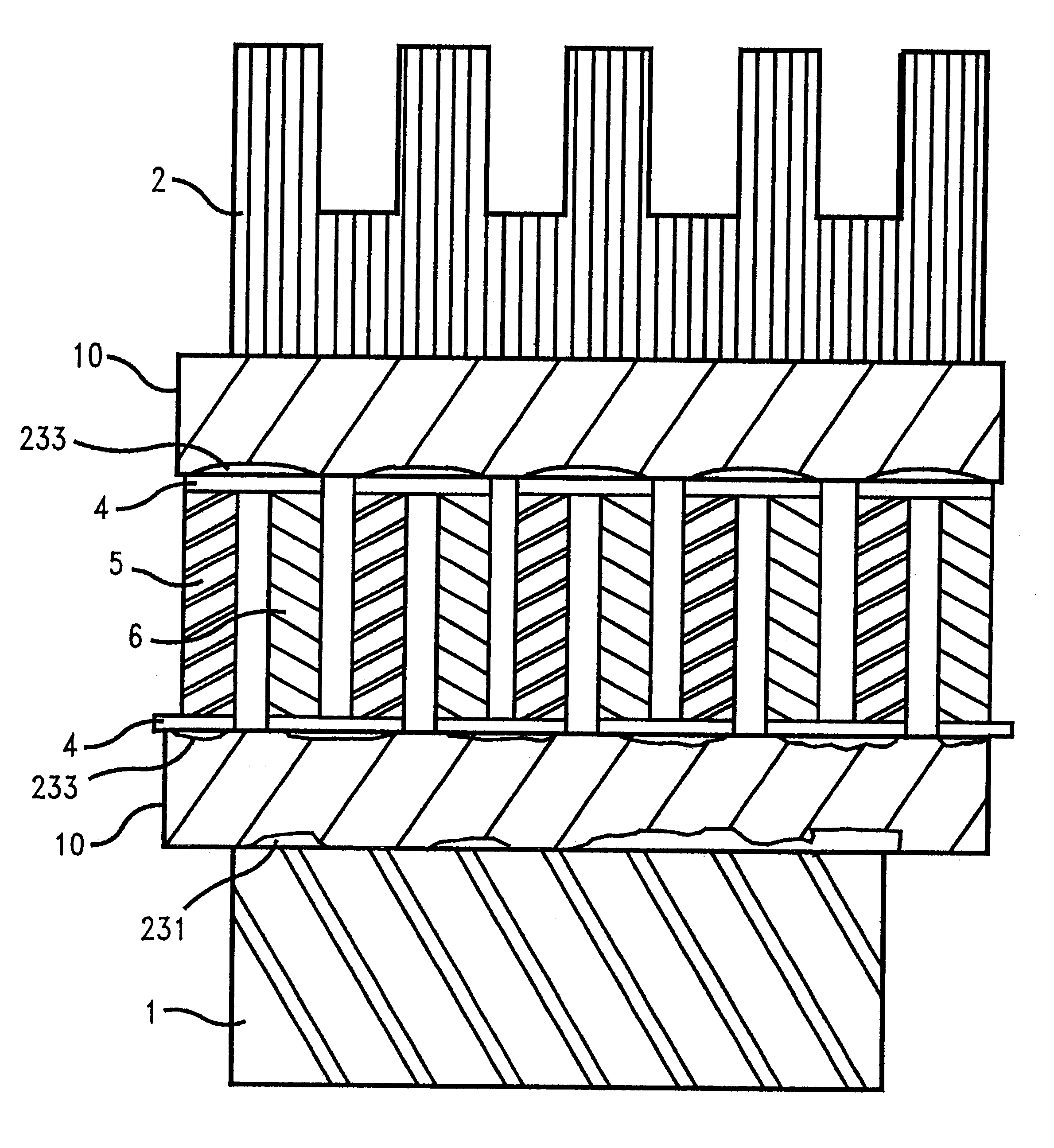
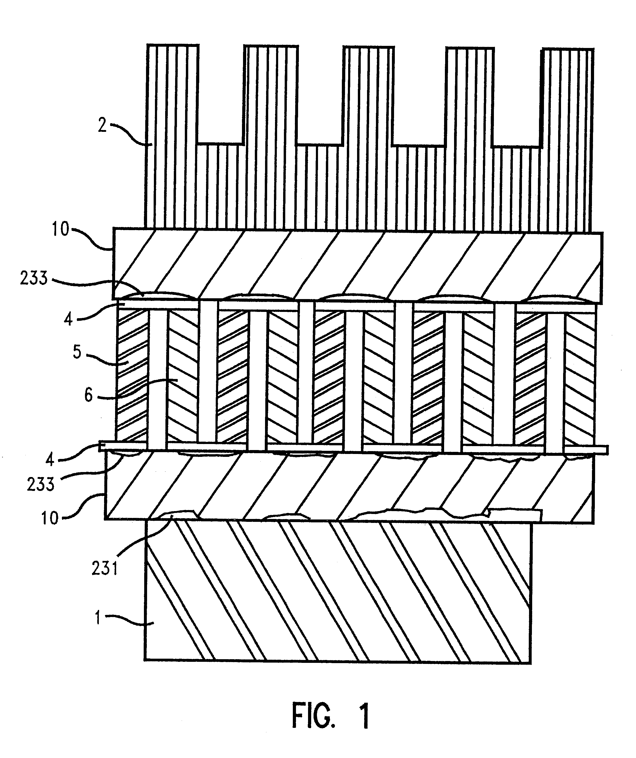
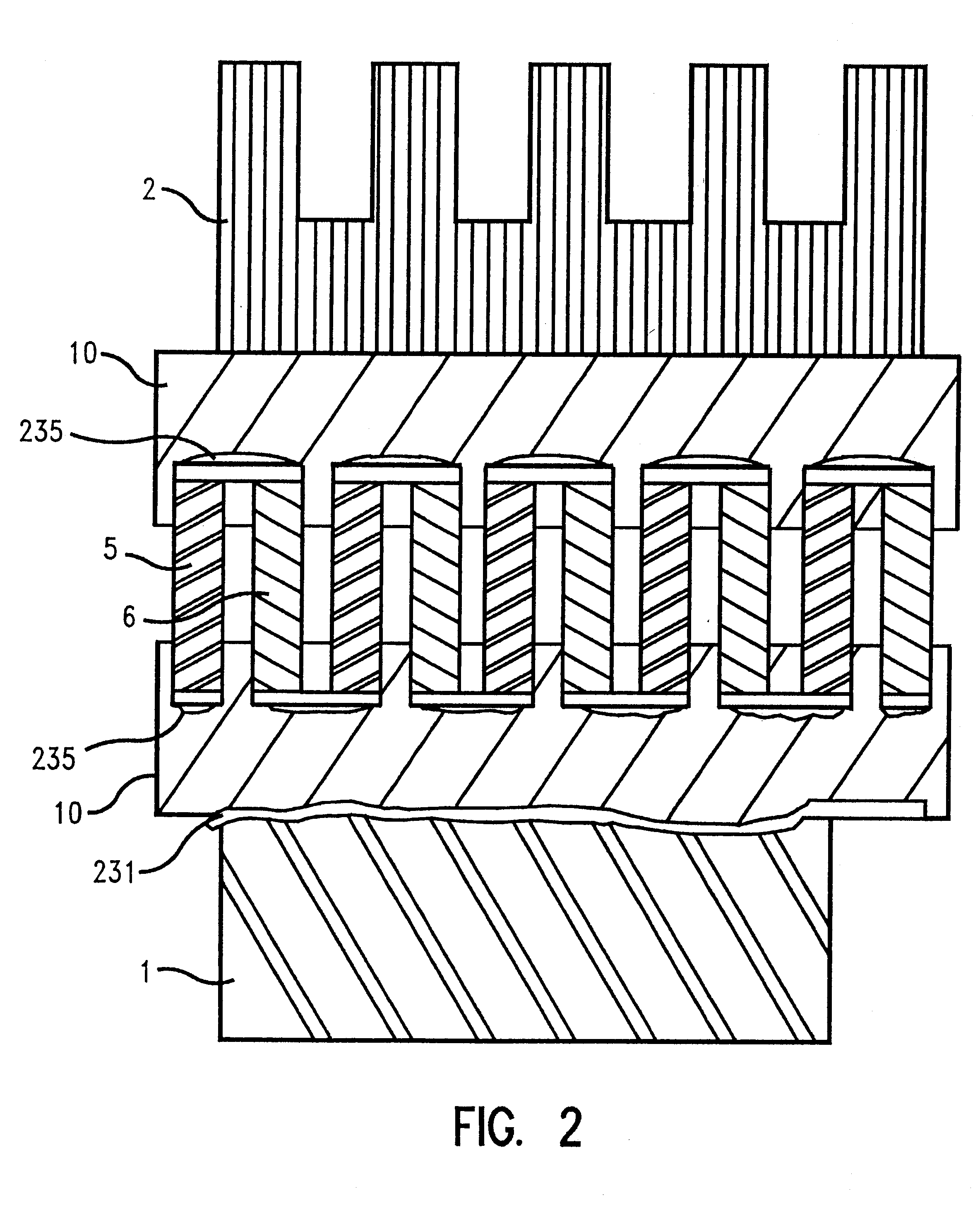
FIG. 1 depicts a thermoelectric device having heat sink 2, alumina faceplates 10, blocks of two different alternating materials 5 and 6 which may be dissimilar metals or different semiconducting materials, and brazed or solder connections 4 residing on top of a layer of refractory metal 233 on the faceplates 10. The refractory metal 233 may either be applied in a post-fire application or screened as a pad on a ceramic greensheet before sintering. The object to be cooled 1, typically an integrated circuit device, resides on the side of the thermoelectric device opposite heat sink 2. The semiconducting materials 5, 6 alternate within the structure, and are situated thermally in parallel. Electrica...


PUM

PropertyMeasurementUnit
temperaturesaaaaaaaaaa
thermal conductivityaaaaaaaaaa
heat absorptionaaaaaaaaaa

Abstract

Thermoelectric devices having enhanced thermal characteristics are fabricated using multilayer ceramic (MLC) technology methods. Aluminum nitride faceplates with embedded electrical connections provide the electrical series configuration for alternating dissimilar semiconducting materials. Embedded electrical connections are formed by vias and lines in the faceplate. Methods for forming tunnels through lamination and etching are employed. A portion of the dissimilar materials are then melted within the tunnels to form a bond. Thermal conductivity of the faceplate is enhanced by adding electrically isolated vias to one surface, filled with high thermal conductivity metal paste. A low thermal conductivity material is also introduced between the two high thermal conductivity material faceplates.Alternating semiconducting materials are introduced within the varying thermal conductivity layers by punching vias within greensheets of predetermined thermal conductivity and filling with n-type and p-type paste. Alternating semiconducting materials may also be patterned in linear or radial fanout patterns through screening techniques and lamination of wire structures. A liquid channel within the faceplate is used to enhance thermal energy transfer.Thermoelectric devices are physically incorporated within the IC package using MLC technology.

Description

1. Field of the InventionThe present invention is related to solid-state electronic heat pumps, commonly referred to as thermoelectric devices. More particularly, the present invention is related to different thermoelectric device configurations and the methods for making the same.2. Description of Related ArtA thermoelectric device is capable of generating electricity if its two ends are held at different temperatures. Conversely, applied electrical current will induce a temperature differential between its two ends. Thus, a thermoelectric device is a heat pump which transfers heat by electric current. The principles of thermoelectricity are utilized in power generation, thermocouples, and refrigeration.Current designs of commercially available thermoelectric devices have efficiencies too low to warrant use in cooling applications with high power microcircuits. However, the use of high thermal conductivity materials along with unique applications of multilayer ceramic technology ma...

Claims


Application Information

Patent Timeline
Patent Type & Authority Patents(United States)
IPC IPC(8): H01L23/38H01L35/32H01L23/34
CPCH01L23/38H01L35/32H01L2924/09701H01L2224/16225H01L2224/48091H01L2924/00014H10N10/17H01L2224/0401
Inventor JOHNSON, GREGORY M.CASEY, JON A.DWYER, SCOTT R.LONG, DAVID C.PRETTYMAN, KEVIN M.
Owner INT BUSINESS MASCH CORP
Why Eureka
Try Eureka