
Purification process

Inactive Publication Date: 2001-07-24
LYONDELL CHEM TECH LP
View PDF8 Cites 18 Cited by
  • Summary
  • Abstract
  • Description
  • Claims
  • Application Information

AI Technical Summary

Benefits of technology

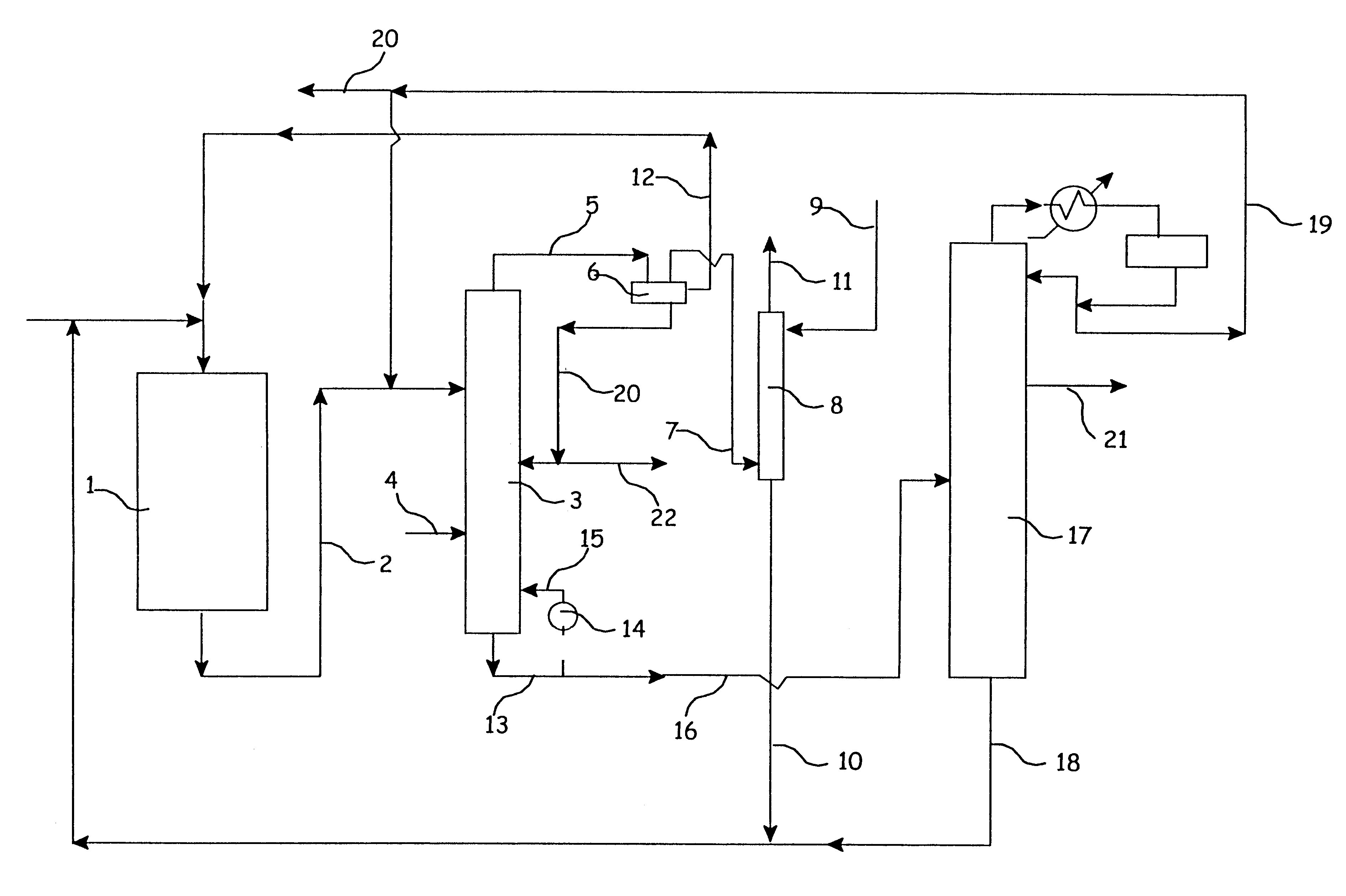
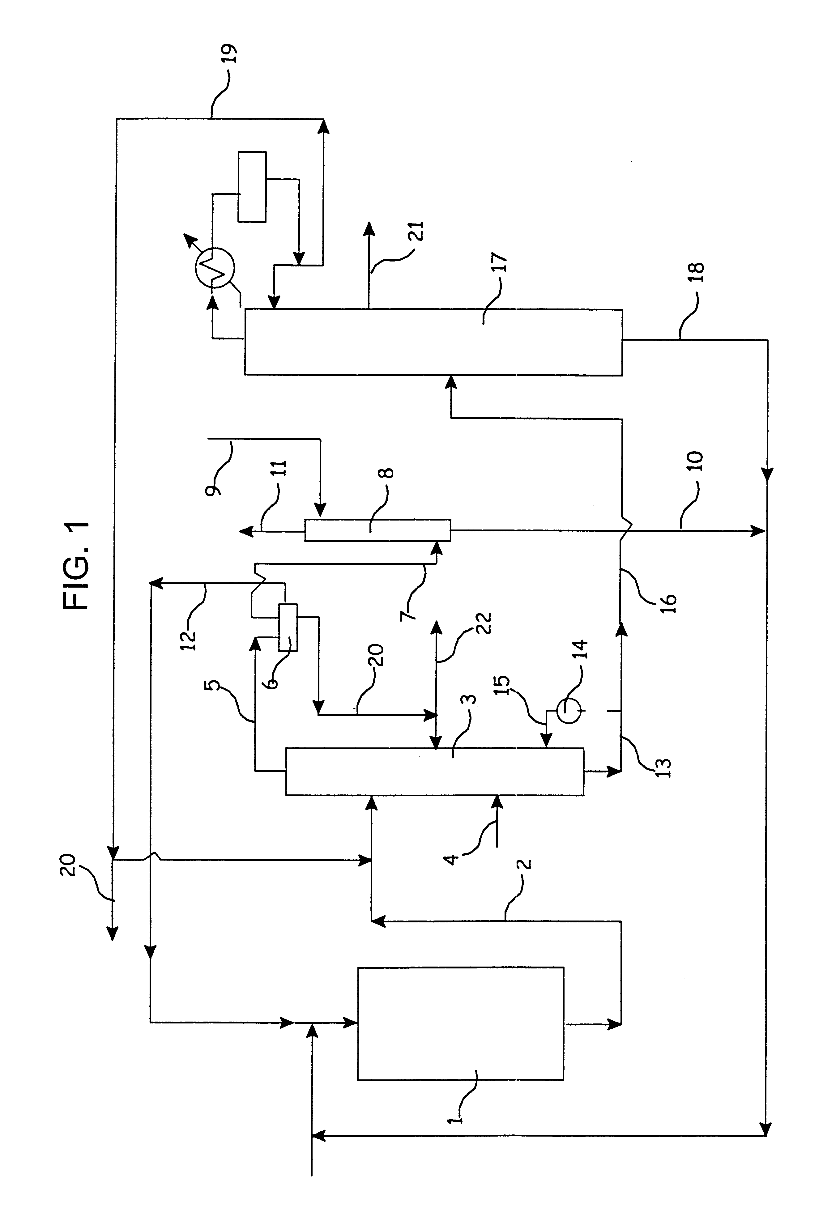
In accordance with the invention, the DPTB to be purified is fed to the upper section of a fractional distillation column, while a stripping component comprised of liquid water or steam is fed to the column preferably at a point below the point of introduction of the mixture to be purified. It is important that DPG also be fed to the column, usually in admixture with the DPTB. The water or steam stream may be introduced into the bottom of the column as a preferred practice although this steam can be introduced at any point. A reboiler is provided wherein bottoms from the column is vaporized and circulated to the column thus providing heat to the column. Heat input into the column via the reboiler is sufficient to ensure vaporization of the liquid water stripping component stream introduced to the column, and the pressure maintained in the column is effective to prevent overheating especially in the reboiler, while maintaining stripping vapor flow upwardly through the column. The stripping component, e.g. water, with some DPTB plus undesirable di-ether impurities as well as unreacted isobutylene is removed overhead, DPTB product substantially reduced in di-ether is removed as bottoms in admixture with DPG. A portion or all of the water phase from the overhead condensate can be returned to the column as stripping water.
The aqueous phase rich in DPTB and DPG is returned to the column to supply the stripping water and to return the DPG and DPTB to the column thus minimizing their loss. A small purge of the aqueous phase is taken as needed.

Problems solved by technology

A problem with such procedures is that certain amounts of di-propylene glycol di-tert-butyl ether are also produced which must be separated from DPTB prior to use of the DPTB as a concrete additive since the di-ether has a pronounced adverse effect in the usage in concrete.
Currently a costly and tedious extractive distillation technology involving the use of two columns and very large recycle streams is employed to accomplish the separation; see U.S. Pat. No. 5,552,024.
Various methods are known for separating minor amounts of impurities from various products including azeotropic and extractive distillation procedures but such prior methods are generally complicated and expensive.
Steam stripping techniques have been employed but tend to result in the introduction of unwanted impurities with the steam, as well as producing waste water from condensing steam.

Method used


Image

  • Purification process
  • Purification process

Examples


example 2

This example illustrates the removal of di-ethylene glycol di-ethyl ether (DEDE) from a blend of diethylene glycol (DEG), di-ethylene glycol mono-ethyl ether (DEME), and di-ethylene glycol di-ethyl ether.

A stream comprised of 72.5% DEG, 2.5% DEDE and 25% DEME at 280.degree. F. is introduced to the top section of a distillation column with 40 stages of packing; at a rate of 1000 lbs / hr. Water at 212.degree. F. is introduced to the bottom section of the column at a rate of 50 lb / hr. Bottoms temperature is maintained at 380.degree. F. while the temperature at the top of the column is 336.degree. F. An overhead vapor stream is taken from the top of the column to a condenser at a rate of 350 lbs / hr and, after condensation, the condensate is separated into two liquid phases. The lighter organic phase is withdrawn at a rate of 205 lbs / hr and contains 21% water, 12% DEDE and 67% DEME. The heavier, aqueous phase containing 60% water, 0.4% DEDE, 1.2% DEME and 38% DEG is returned to the bottom...


PUM


Abstract

A procedure is provided for the separation of close boiling impurities from products which have slightly higher polarity than the impurities, for example, separation of di-propylene glycol di-tert-butyl ether (DE) from di-propylene glycol mono-tert-butyl ether (DPTB) by distillation, water or steam being used as stripping component with heat provided by a reboiler.

Description

1. Field of the InventionThe present invention relates to the separation of glycol di-alkyl ethers from the corresponding mono-ethers, especially to the preparation of high purity di-propylene glycol mono-tert-butyl ether (DPTB) by the separation of impurities such as di-propylene glycol di-tert-butyl ether (DE) from the DPTB.2. Description of the Prior ArtDi-propylene glycol mono-tert-butyl ether (DPTB) is used commercially as a solvent and, in combination with dipropylene glycol as a concrete additive.A commercial process for the production of DPTB involves reacting di-propylene glycol (DPG) with isobutylene over an acid ion exchange resin catalyst. A problem with such procedures is that certain amounts of di-propylene glycol di-tert-butyl ether are also produced which must be separated from DPTB prior to use of the DPTB as a concrete additive since the di-ether has a pronounced adverse effect in the usage in concrete.Currently a costly and tedious extractive distillation technolo...

Claims


Application Information

Patent Timeline
IPC IPC(8): B01D3/34B01D3/38B01D3/14C07C41/00C07C41/42
CPCB01D3/143B01D3/38C07C41/42C07C43/11Y10S203/11
Inventor GUPTA, VIJAI P.
Owner LYONDELL CHEM TECH LP
Learn More