Suction apparatus of multi-cylinder internal combustion engine

a multi-cylinder internal combustion engine and suction apparatus technology, which is applied in the direction of machines/engines, combustion air/fuel air treatment, and suction characteristics, etc., can solve the problems of deterioration of difficult improvement of the suction characteristic in the middle and high rotative speed region by utilizing resonance supercharging effect, and the effect of reducing the acoustic commercial quality of the engin

Inactive Publication Date: 2001-07-31
HONDA MOTOR CO LTD
View PDF9 Cites 16 Cited by
  • Summary
  • Abstract
  • Description
  • Claims
  • Application Information

AI Technical Summary

Problems solved by technology

Since the connecting pipe for connecting the resonance vessel to the gathering section of the independent suction passages is long, though suction characteristic in a low rotative speed region can be improved, improvement of suction characteristic in middle and high rotative speed region by utilizing resonance supercharging effect is difficult because enlargement of diameter of the connecting pipe is limited.
Further, since the resonance vessel is fixedly connected to the flanges of the independent suction passages, vibration of the engine main body is directly transmitted to the resonance vessel and the resonance vessel generates secondary radiating sound so that deterioration of acoustic commercial quality of the engine is feared and stabilization of suction characteristic in resonance supercharging utilizing the resonance chamber is liable to be injured.
With respect to the suction manifold itself, since a mass vibrating with the same p...

Method used


Image

  • Suction apparatus of multi-cylinder internal combustion engine
  • Suction apparatus of multi-cylinder internal combustion engine
  • Suction apparatus of multi-cylinder internal combustion engine

Examples


Embodiment Construction

Hereinafter, a preferred embodiment of the present invention will be described with reference to FIGS. 1 to 9.

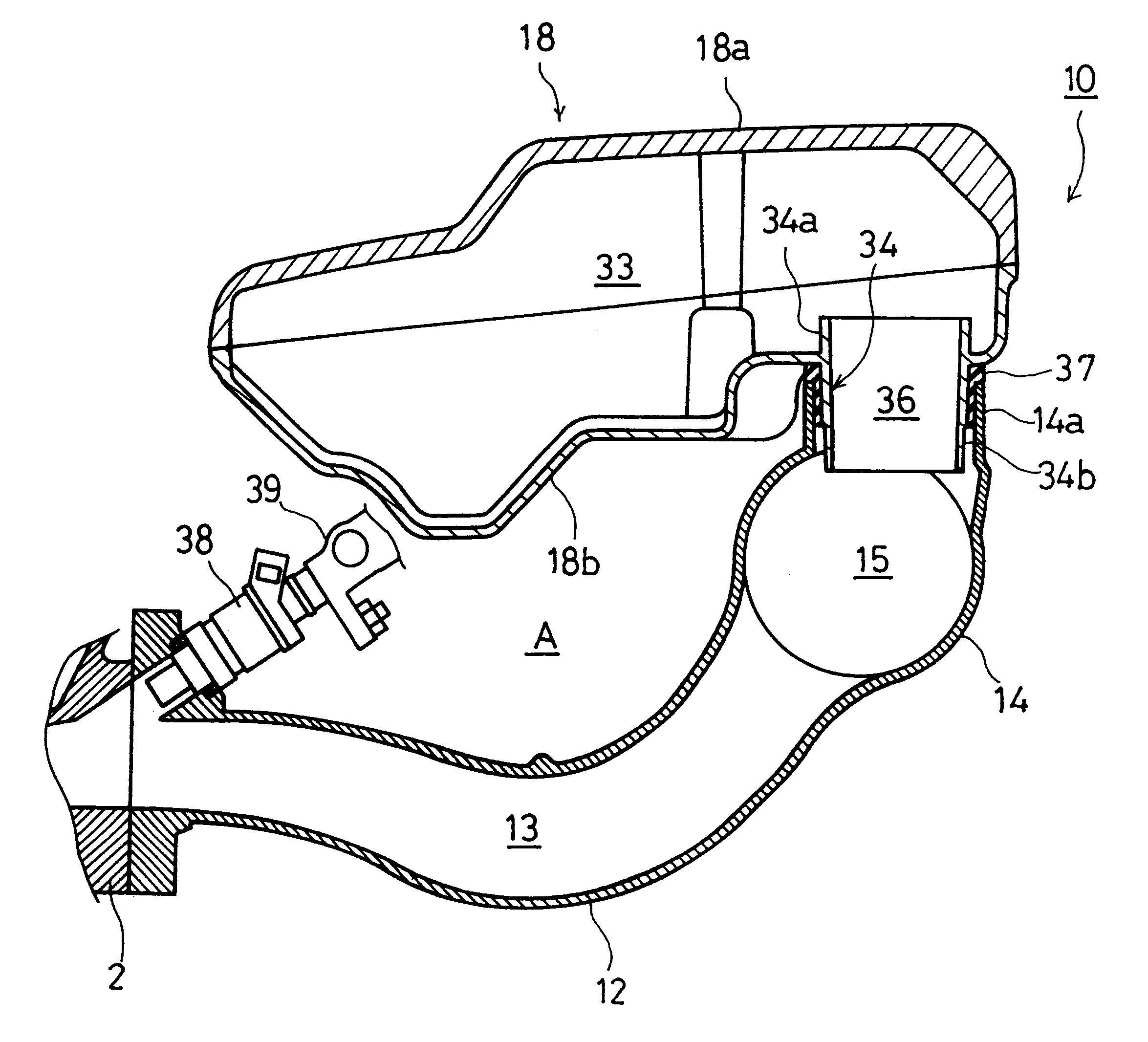
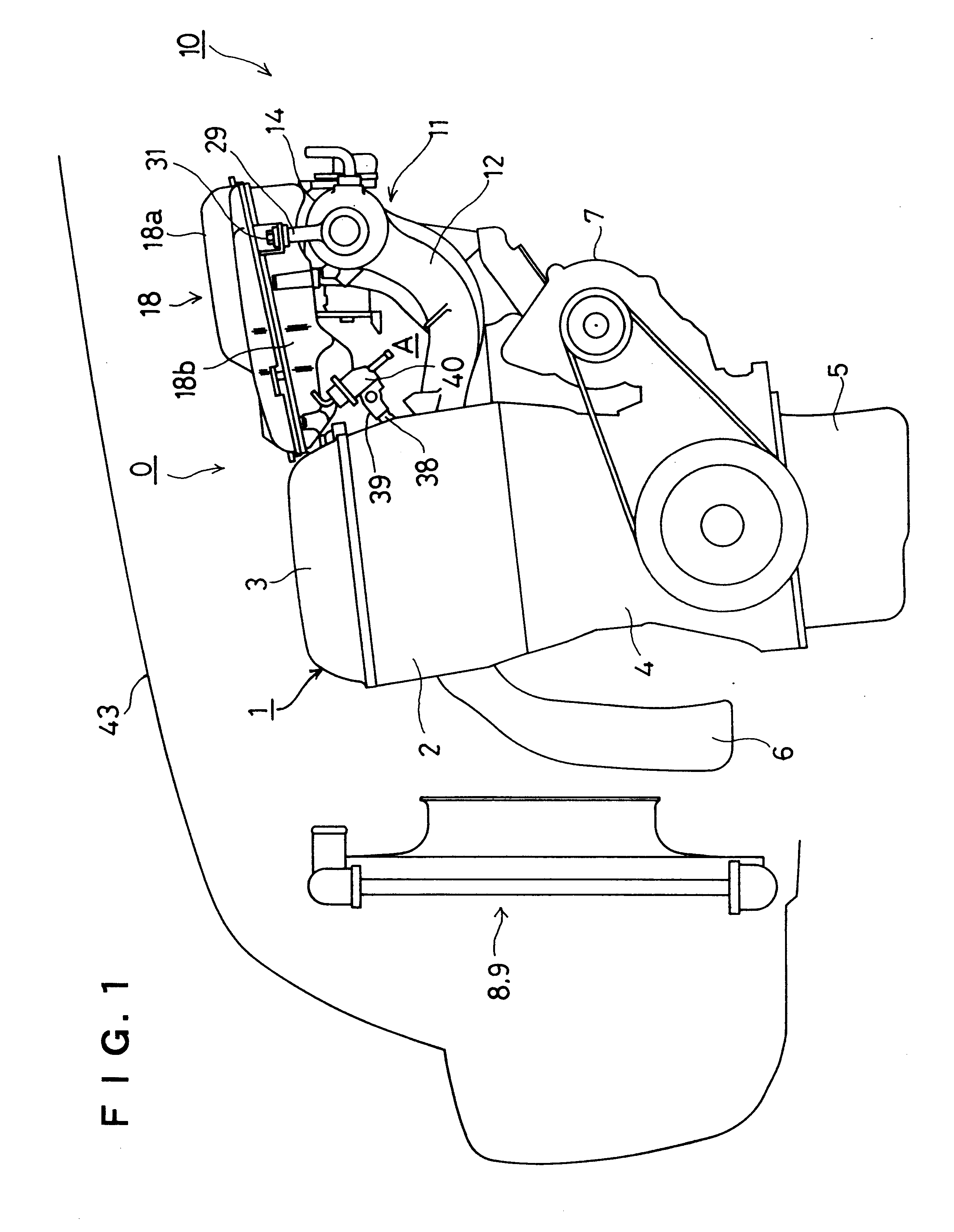
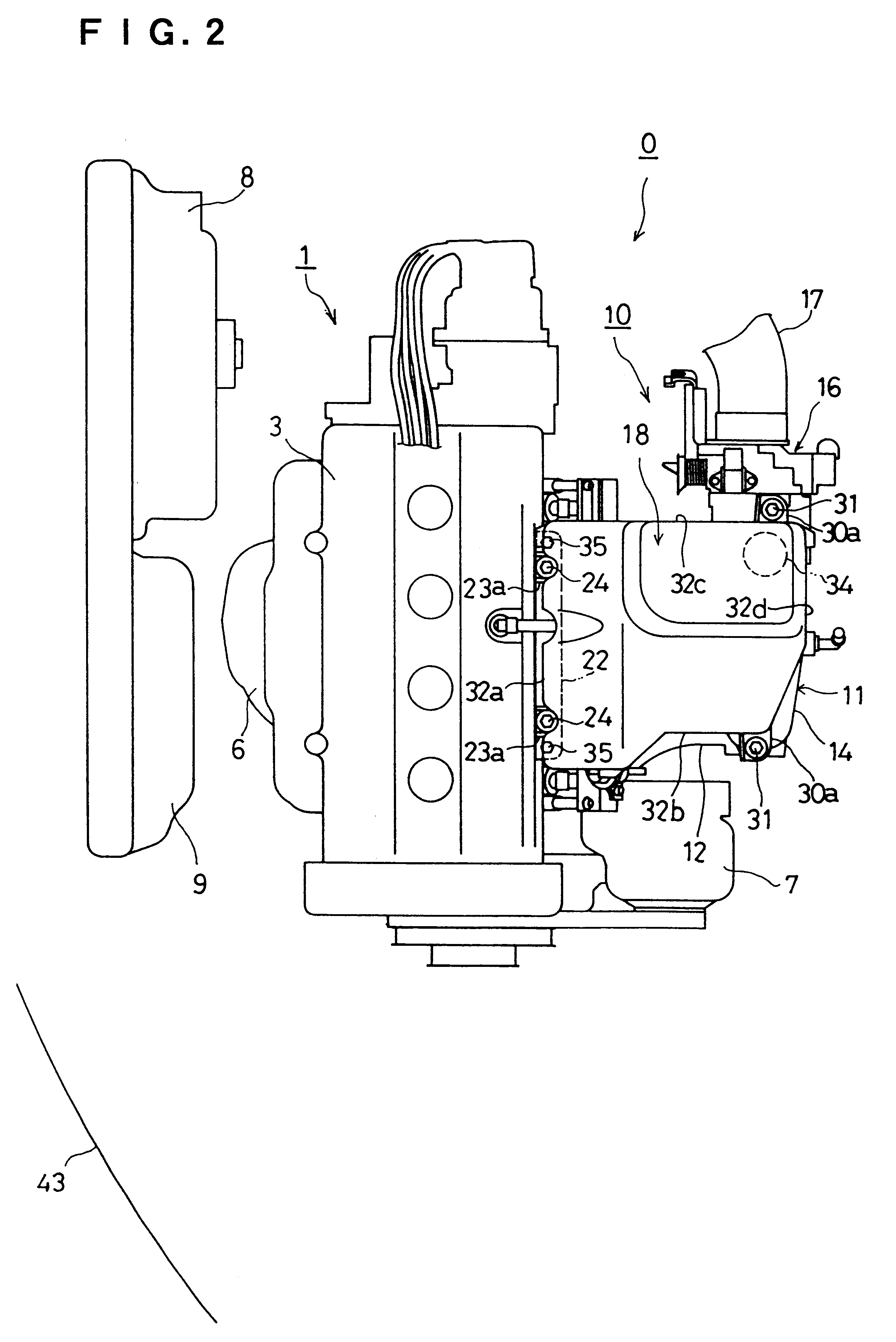
The multi-cylinder internal combustion engine 0 having a suction apparatus 10 according to the preferred embodiment of the invention shown in FIGS. 1 and 2 is a straight-type four cylinder internal combustion engine and mounted on a front part of a vehicle laterally, namely, having a crankshaft directed breadthwise of the vehicle. The engine 0 comprises an engine main body 1 having a cylinder block 4, cylinder head 2, cylinder head cover 3 and an oil pan 5 provided under the cylinder block 4, a suction apparatus 10 disposed in rear of the engine main body 1, and an exhaust manifold 6 disposed in front of the engine main body 1 along a row of cylinders over the cylinder head 2 and the cylinder block 4. In front of the exhaust manifold 6 are provided a radiator 8 and a condenser 9.

The suction apparatus 10 includes a suction manifold 11 disposed in rear of the cylinder head 2 a...


PUM


Abstract

A suction apparatus of a multi-cylinder internal combustion engine has a suction manifold disposed in a direction parallel with a row of cylinders at one side of a cylinder head. The suction apparatus includes a plurality of independent suction passages of equal length each extending from an engine main body at right angle, a suction gathering chamber connected to the suction passages and disposed in the direction parallel with the row of cylinders, a throttle body provided at an upper stream end of the suction gathering chamber, and a resonance vessel communicating with the suction gathering chamber. The resonance vessel is supported by a cylinder head cover and a wall of the gathering chamber elastically through rubber members covering above of the independent suction passages with a space, and communicates with an upper part of the suction gathering chamber at a just downstream position of the throttle body. The space has a volume capable of receiving at least fuel injection valves and fuel supply pipes for respective cylinders of the internal combustion engine.

Description

1. Field of the InventionThe present invention relates to a suction apparatus of a multi-cylinder internal combustion engine, particularly to such a suction apparatus having a plurality of independent suction passages of equal length.2. Description of the Related ArtIn a multi-cylinder internal combustion engine for a vehicle, it has been practiced generally to change passage length or volume of a suction pipe in accordance with rotative speed of the internal combustion engine for utilizing inertia supercharging effect and resonance (pulsation) supercharging effect of suction air in order to maintain high volumetric efficiency over a wide rotative speed region from a low rotative speed region to a high rotative speed region.Japanese Laid-Open Patent Publication No. 7-91263 discloses such a multi-cylinder internal combustion engine which has a resonance vessel attached to a suction passage to improve resonance supercharging effect of suction air particularly in a low speed region.Thi...

Claims


Application Information

Patent Timeline
IPC IPC(8): F02F7/00F02M35/10
CPCF02F7/006F02M35/10052F02M35/10144F02M35/10295F02M35/112F02M35/1255F02M35/1283F02B27/021F02B27/0252F02M35/10039F02B27/0273F02M35/10065F02M35/10072F02M35/10229Y02T10/146Y02T10/12
Inventor MATSUMOTO, YUKIHIROWATAHIKI, TOSHIYAAOSHIMA, TOSHIHARUOHMORI, TADANOBUYAMAGUCHI, KYOKOTSUKII, TSUTOMU
Owner HONDA MOTOR CO LTD
Why Eureka
Try Eureka