Airfoil with dynamic stall control by oscillatory forcing

a technology of oscillatory force and airfoil, which is applied in the field of airfoil, can solve the problems of high maintenance cost, low maximum flight speed, and limited maneuverability

Inactive Publication Date: 2001-07-31
RAMOT UNIV AUTHORITY FOR APPLIED RES & INDAL DEVMENT
View PDF11 Cites 65 Cited by
  • Summary
  • Abstract
  • Description
  • Claims
  • Application Information

AI Technical Summary

Problems solved by technology

These capabilities, however, are accompanied by severe limitations such as relatively low maximum flight speeds (typically 150 knots), maneuverability limitations, as well as high maintenance costs resulting from large oscillatory loads on the rotor mechanism.
Dynamic stall is a highly complex phenomenon containing the traditional problems of transition, turbulence, separation, reattachment, etc., all encapsulated in an unsteady and sometimes three-dimensional and compressible environment.
As a natural consequence of its complexity, dynamic stall creates a major problem for helicopter rotor designers.
The root of the design problem is an incomplete understanding of the fundamental mechanisms which give rise to the flow structures which characterize dynamic stall.
This lack of understanding translates directly into severe limitations in the prediction of rotor-loads, which manifests as a major rotor design constraint.
These attempts at containing the DSV a...

Method used


Image

  • Airfoil with dynamic stall control by oscillatory forcing
  • Airfoil with dynamic stall control by oscillatory forcing
  • Airfoil with dynamic stall control by oscillatory forcing

Examples


Embodiment Construction

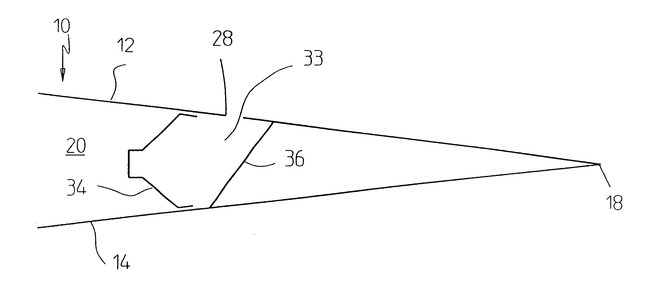
All dynamic stall experiments were carried out on a 365 mm NACA0015 airfoil--a schematic cross section of which is shown in FIG. 3. Airfoil 10' was equipped with 36 pressure taps (not shown) and incorporated a flap 60 whose axis 62 was located at the 75% chord position. The flap angle (.delta..sub..function.) could be deflected in the range -10.degree. to 30.degree.. The main body of airfoil 10' was essentially hollow with interior 20 serving as a plenum chamber. Two slots were employed independently (never simultaneously) for forcing and blowing, namely: a 1 mm slot 64 at the leading-edge and a 1.5 mm slot 66 at the flap-shoulder. The slot not in use was closed either internally or by means of tape on the airfoil surface.

All dynamic pressure measurements were made with a PS4000 multi-channel array of pressure transducers (AA Lab Systems). The pressure transducers were calibrated for amplitude attenuation and phase shift due to the finite length of tubing between each pressure-tap a...


PUM


Abstract

A method for inhibiting dynamic stall of an airfoil by causing a fluid to flow out of at least one location on the airfoil. This location may be anywhere on the airfoil; but if the location is within one-quarter of the airfoil chord from the leading edge and the fluid flow has non-zero net mass flux, then the fluid flow is modulated at a frequency described by a Strouhal ratio greater than one.

Description

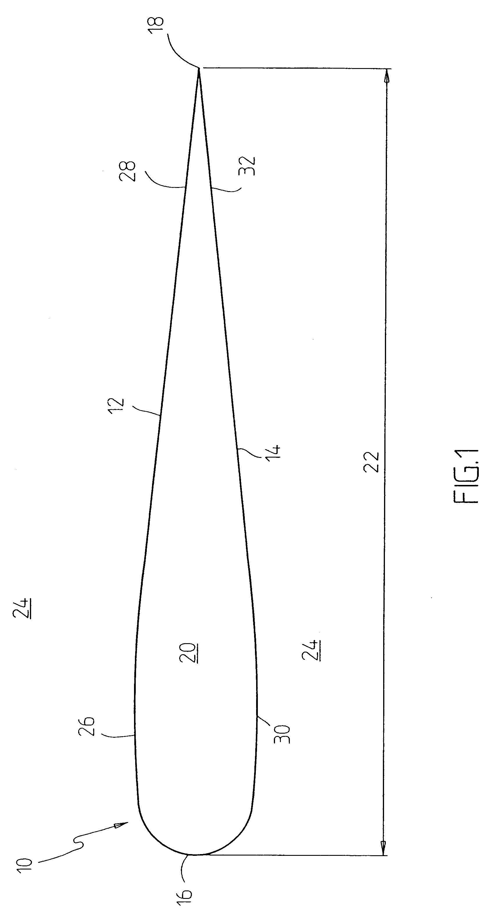
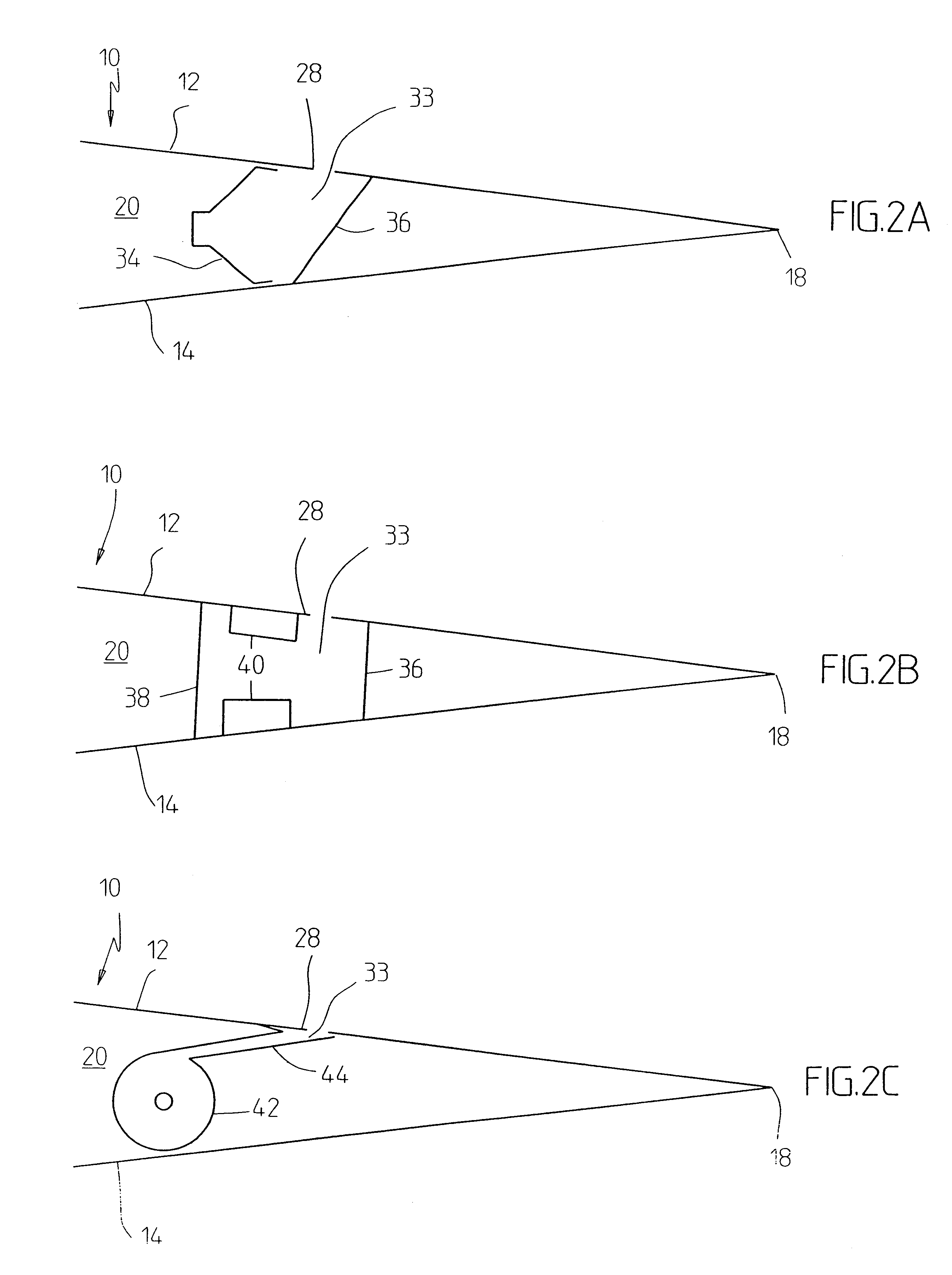
FIELD AND BACKGROUND OF THE INVENTIONThe present invention relates to an airfoil for applications, such as rotary wing aircraft, in which the angle of attack changes rapidly and continuously and, more particularly, to an airfoil designed to control dynamic stall.Rotary wing aircraft have gained wide popularity, both in the military and in commercial applications, primarily because of their vertical takeoff / landing capabilities and their ability to hover. These capabilities, however, are accompanied by severe limitations such as relatively low maximum flight speeds (typically 150 knots), maneuverability limitations, as well as high maintenance costs resulting from large oscillatory loads on the rotor mechanism. These limitations have their source in a phenomenon known as dynamic stall. Dynamic stall is a highly complex phenomenon containing the traditional problems of transition, turbulence, separation, reattachment, etc., all encapsulated in an unsteady and sometimes three-dimension...

Claims


Application Information

Patent Timeline
IPC IPC(8): B64C27/32B64C23/04B64C27/467B64C23/00B64C11/18B64C27/46
CPCB64C21/04B64C21/08B64C23/04B64C27/467B64C2230/04Y02T50/166B64C2230/02B64C2230/06Y02T50/10
Inventor WYGNANSKI, ISRAELGREENBLATT, DAVIDSEIFERT, AVI
Owner RAMOT UNIV AUTHORITY FOR APPLIED RES & INDAL DEVMENT
Why Eureka
Try Eureka